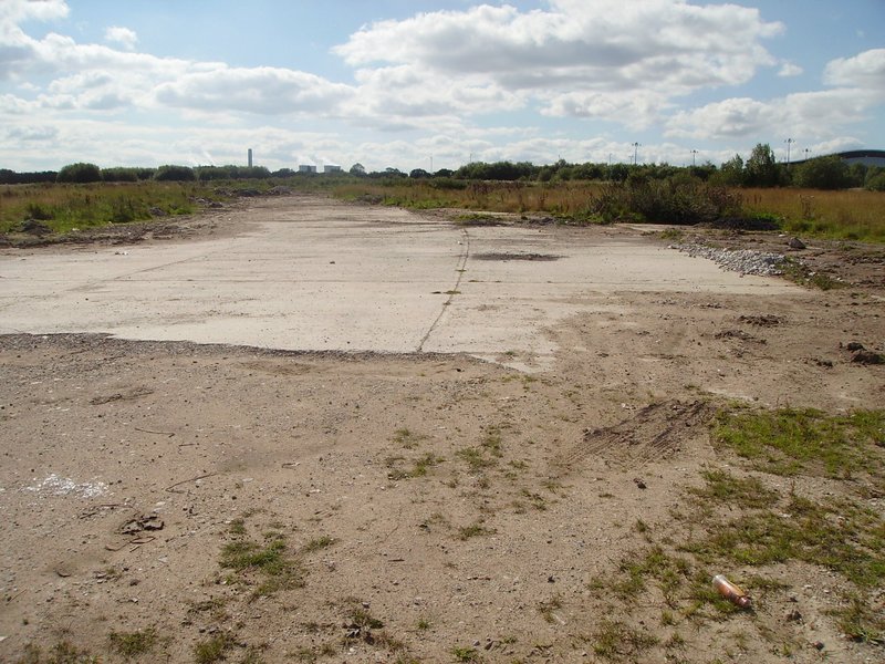
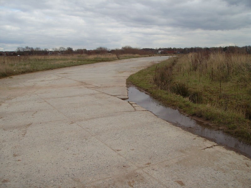
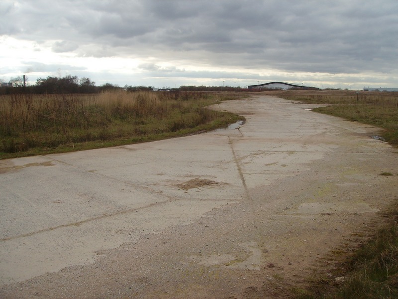
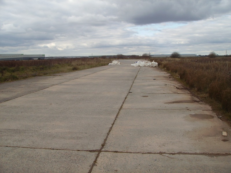
(The Following Photos Were ALL Taken in 2016) The remaining part of the apron in front of the ‘C’ type hangars looking East
Mary Ann site. The curve of the apron (in the distance) goes round to the right and follows the arc of the hangars.
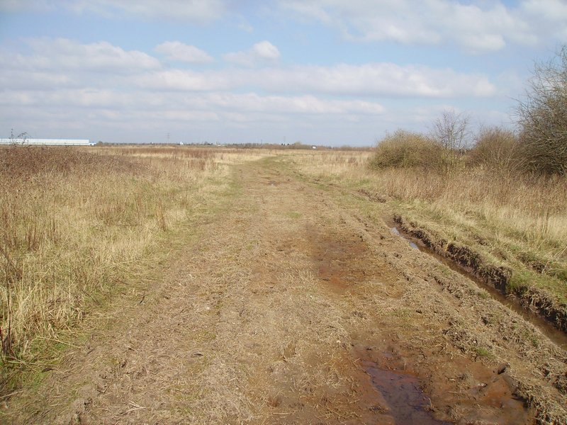
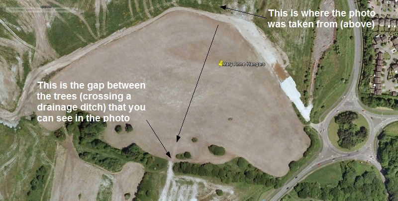
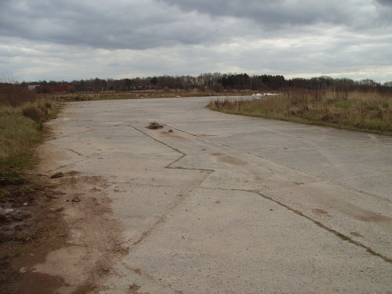
Hangar AD5 was situated just beyond the concrete (in the foreground) AD4 was on the left and AD6 was on the right as you view the photo. Mary Ann site and its associated buildings extended back to the tree line The gap in between the trees in the background was the actual main road leading up to Mary Ann site and contained all 3 hangars.. The main road came from the main entrance and passed through in between the 2 large workshop warehouses building 225 and 226 (beyond the trees in the background) and continued through the gap (in the middle of the photo coming this way) and onto the Mary Ann hangar site.
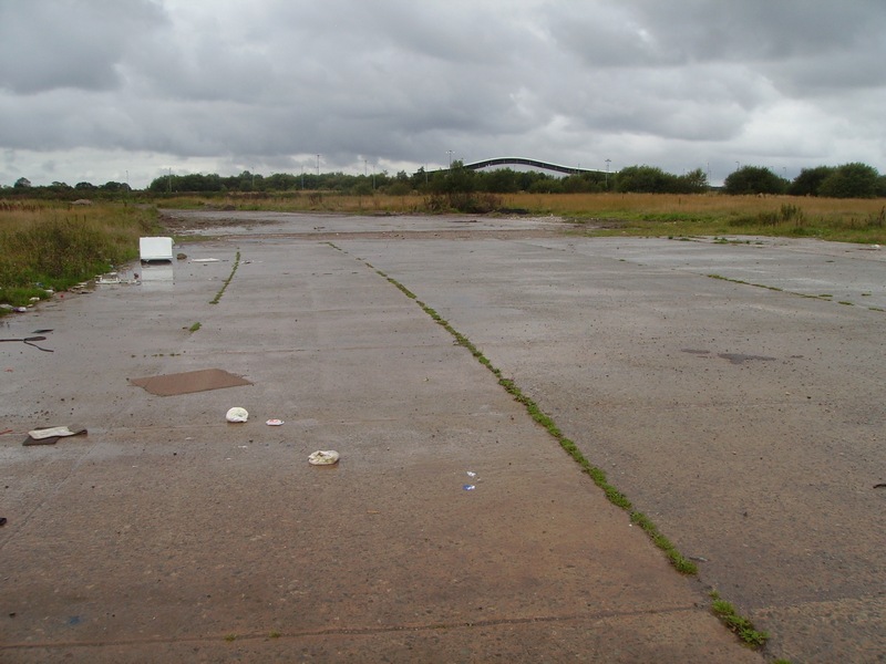
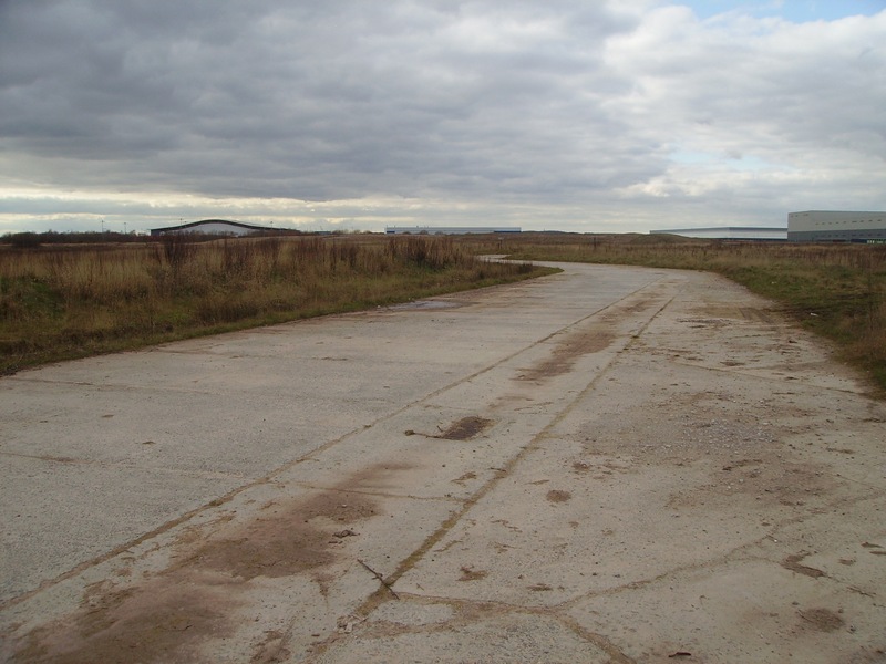
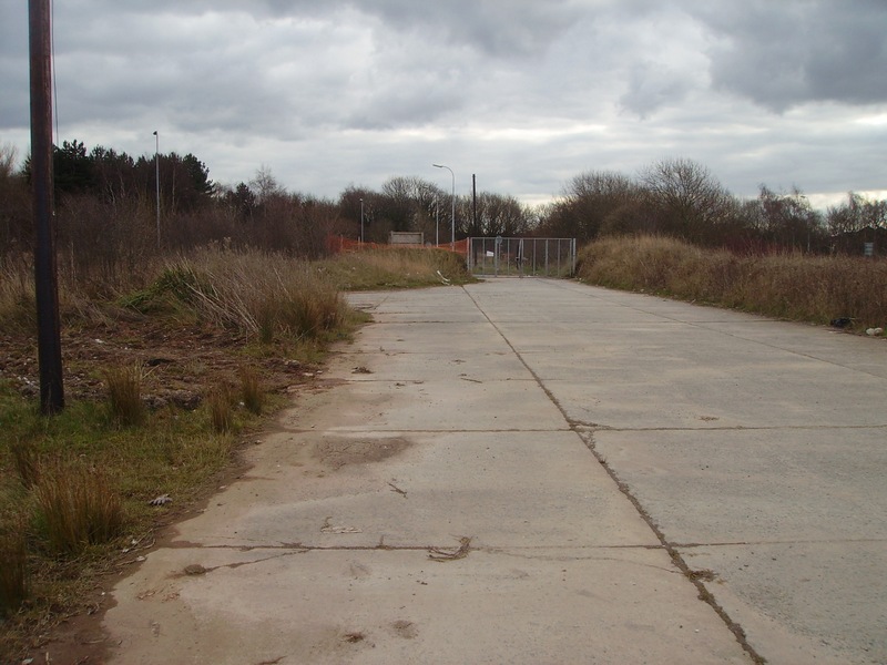
Below (Photo) is the Gap between the trees (as Described above) but Looking NORTH This Originally (During WW2) Was The Perimeter Track To/From Mary Ann Site, but Later was Used as a Main Service Road To The Rear of Mary Ann Site.
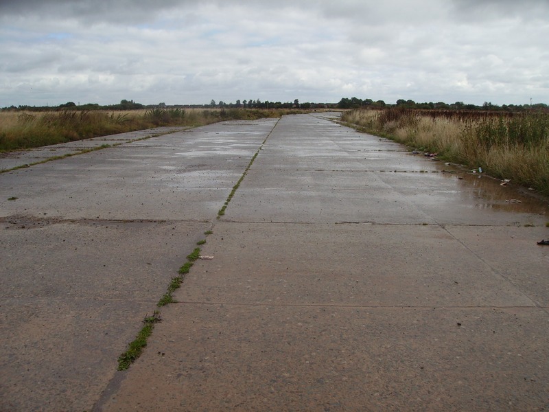
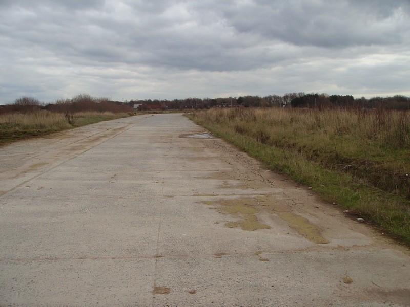
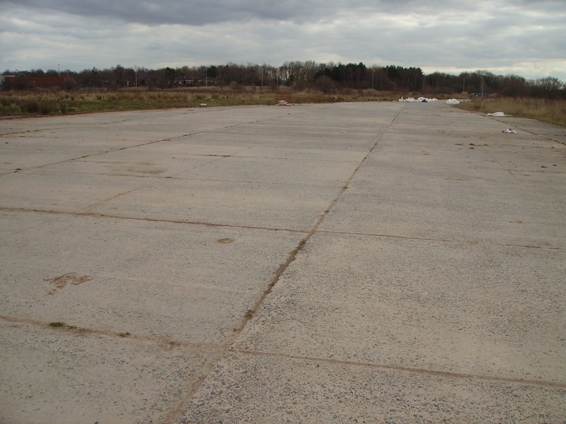
Looking Eastwards at part of the Remaining Apron. The concrete we can see (as a road now) originally extended onto the grassed area that you can see on the left & the ‘C’ Type hangars were on the Right of the concrete.
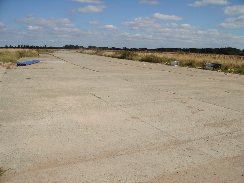
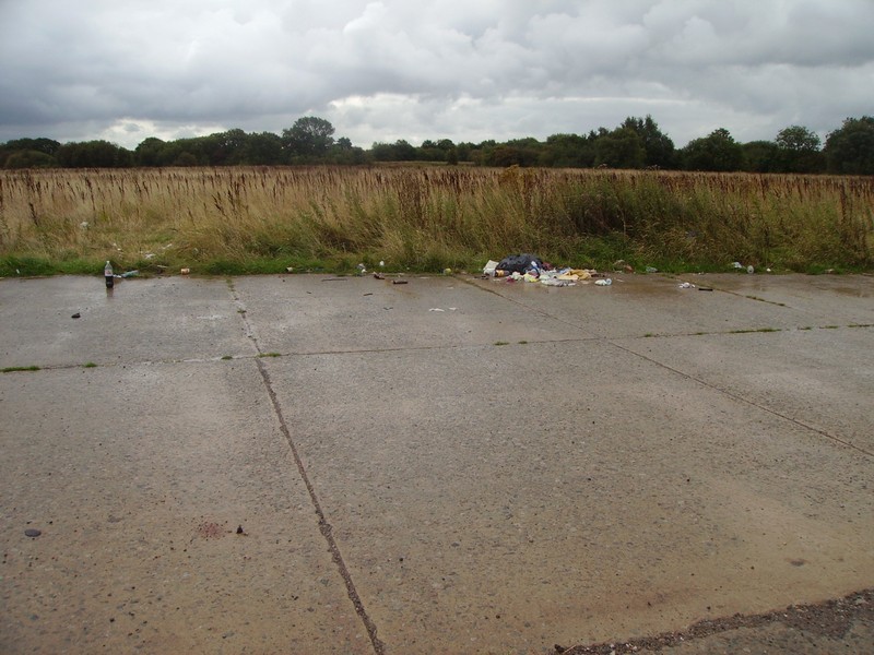
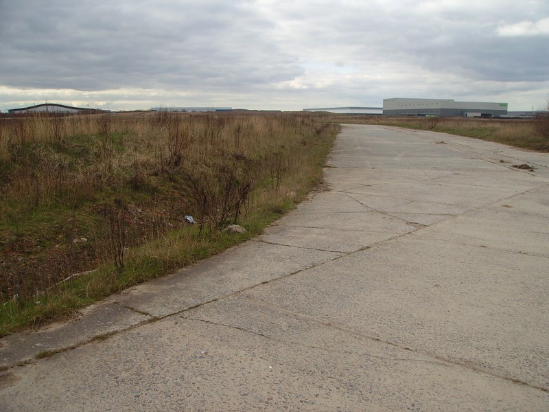
Looking West towards ‘G’ site from the Mary Ann Apron. The large building in the background is the Royal Mail Depot and was originally the site of one of the large warehouse workshops.
Looking West again (but further round) you can see the Royal Mail Depot that was ‘G’ Site & Just to the right is the new Asda building which is built on Technical Site.
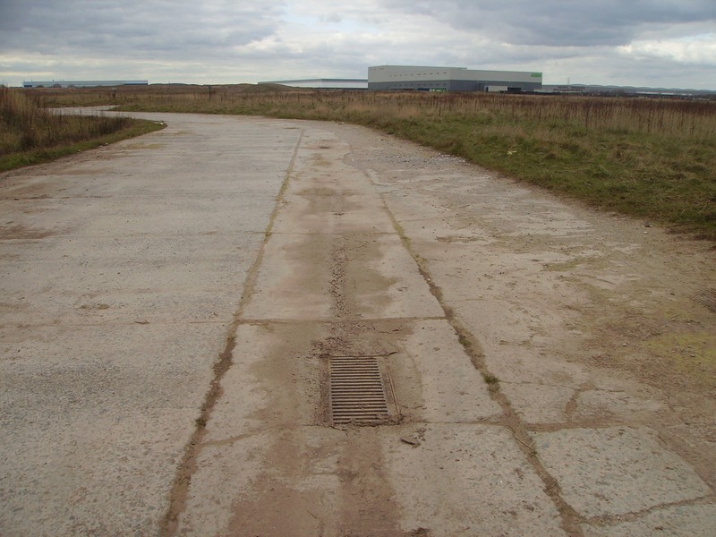
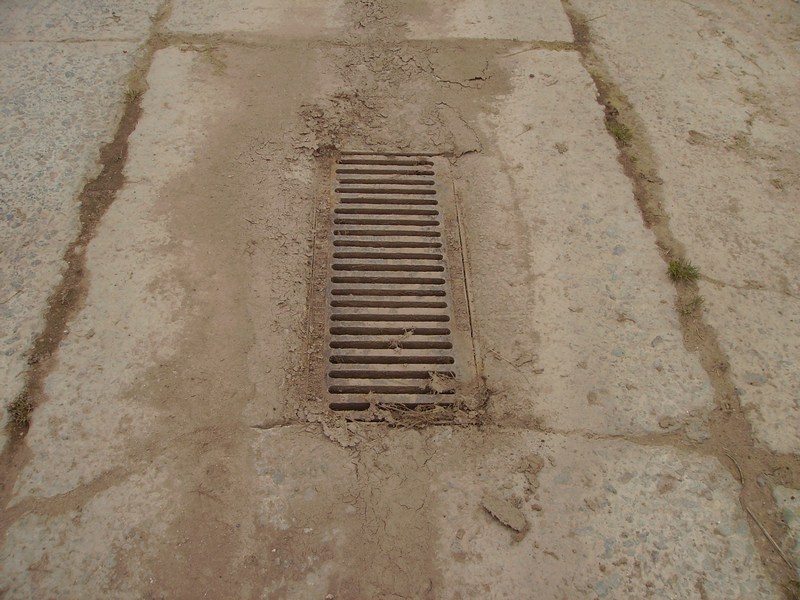
Note the cambered concrete and the grid These grids were spaced out at regular intervals This was to enable the surface water to drain away off the apron
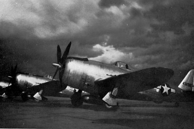
(Note: The following photos are just to show the grids as they were in operation as a working base) RAF Hawker Hunter F.6 XE527/P of number 19 squadron at Church Fenton on the Burtonwood Mary Ann Site Apron on the 17 May 1958 public open day Note the Apron drainage channel and grid in the concrete Photo Credit, James MacKenzie, North West Air News
1954 – 349250 Douglas C-47 AACS Radar calibrator Natural metal, white top Somewhat over-exposed Although Dick Ward gives this a 1956 date, my lists only show 349250 as being at the 1954 Burtonwood public open day I do suspect 1956 could be missing some of the ‘based’ regulars It could be either 1954 or 1956 Note the apron drainage channel and grid in the concrete Photo credit Richard Ward North West Air News
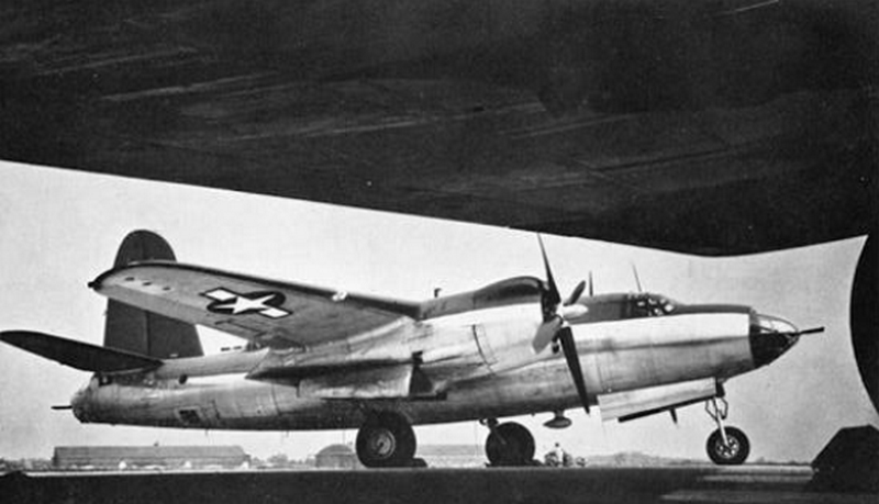
USAF Boeing KB-50P 0-483906 with a Silver overall badge on the tailfin The photo was taken on the Burtonwood Mary Ann Site Apron on a public open day in 1956 Note the C-Type hangar in the background Photo credit Richard Ward North West Air News
RAF Blackburn Beverley C.1. XB268-D of number 47 squadron during the 1956 public open day The 2 K-Type hangars at A-Site can be seen in the background Photo credit R.L. Ward North West Air New
P.O.L. covered storage inside one of the C-Type hangars at Mary Ann Site
Outside P.O.L. storage at Mary Ann Site
Gate 13 Please Note: Gate 13 Was Situated on Burtonwood Road (where the roundabout is now) & Not Where The Gate is on the Photo Below. It was (roughly speaking) where the trees are on this photo past the gate you can see.
Looking North Westerly From Gate 13. The Asda Building on the Left of the Photo was Where Technical Site & The Large Warehouse on the Right is ‘E’ Site and is on the Other side of the M62. The M62 was the Actual Main Runway 09/27
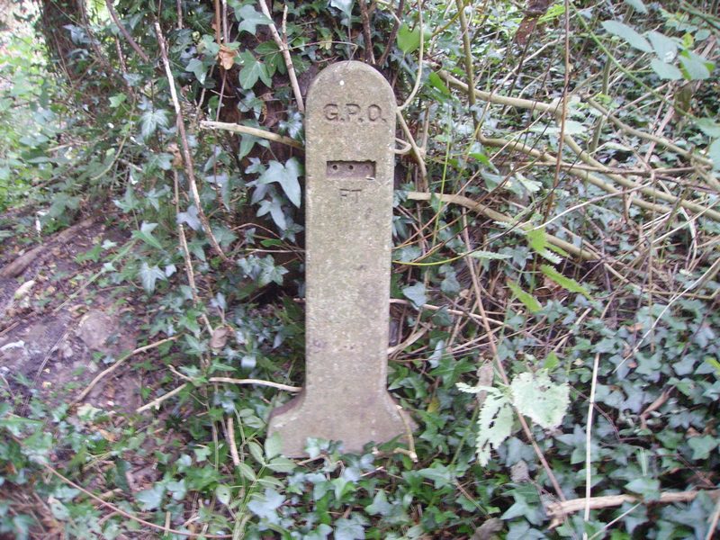
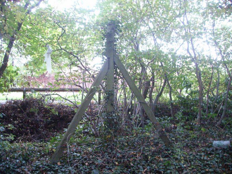
The following photos (below) are from what remains of a small group of buildings between Hangar 17 & the large Workshop Warehouse 2 A GPO (General Post Office) Underground Telephone Cable Line Marker Note: The small rectangle you can see below the G.P.O. letters (typically) had a metal plate inserted in it showing the depth of the cable stamped on it. (A Reminder that All The Photos Were Taken in 2016)
Lead Sheathed Paper Insulated Multi Core Telephone Cable Encased in a Steel Sleeve to Support it Crossing The Drainage Ditch
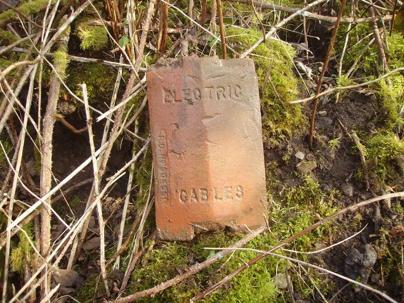
Underground Electrical Cable ‘Location Marker’ Tile. These type of tiles were connected together & laid ‘along’ the length of the electrical cables to ‘mark’ that electrical cables were present underneath them and also for protection
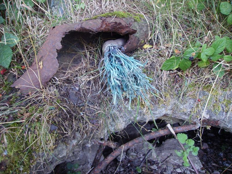
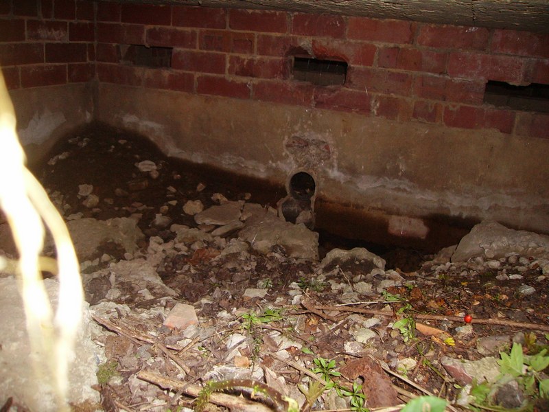
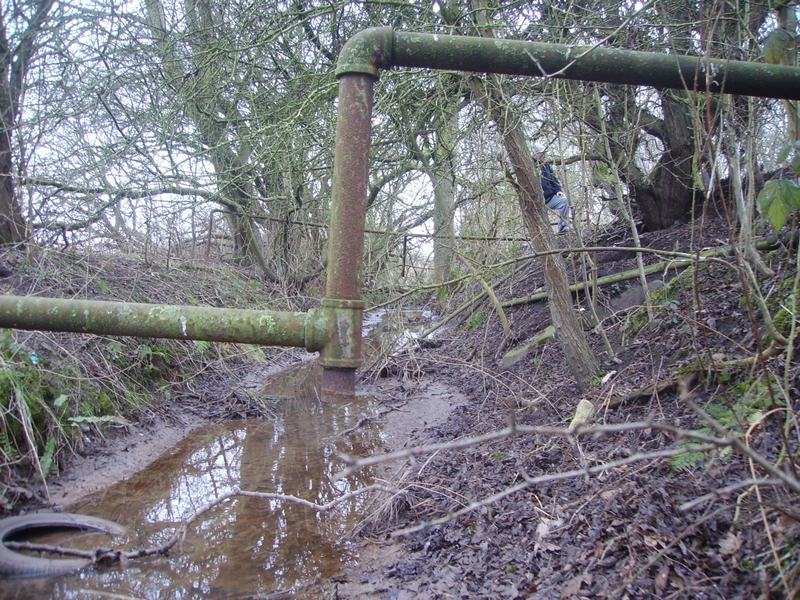
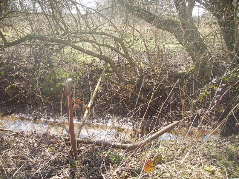
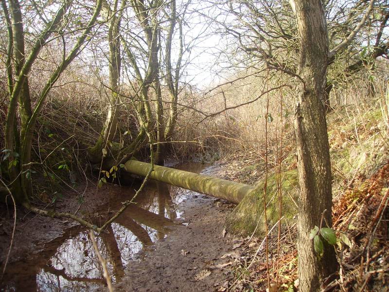
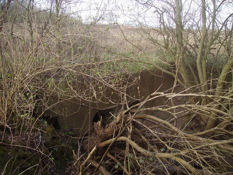
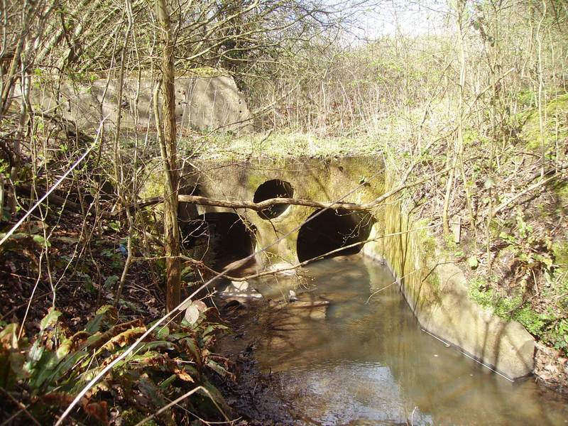
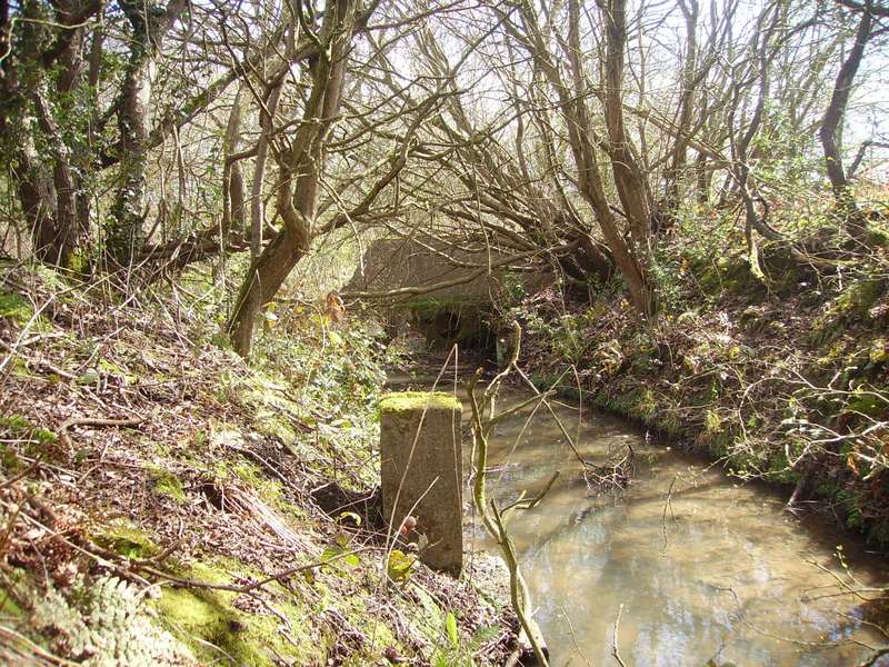
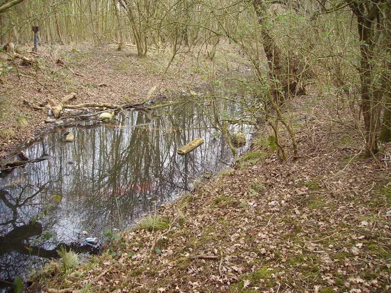
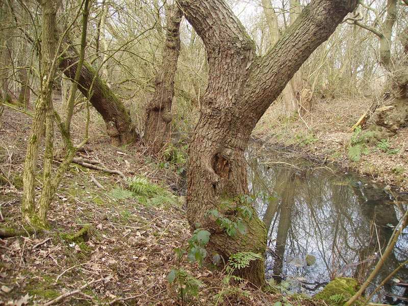
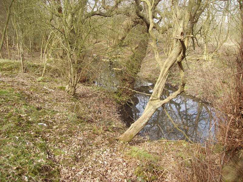
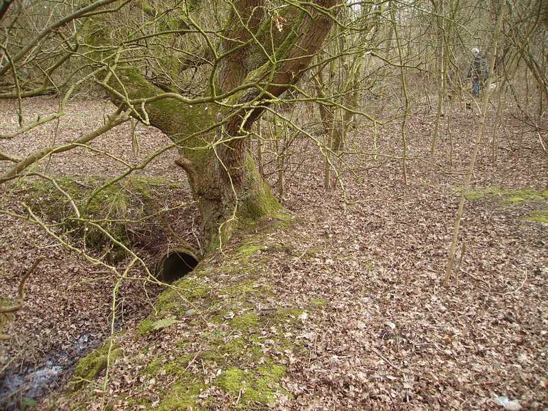
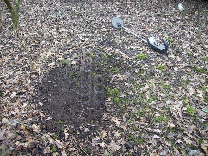
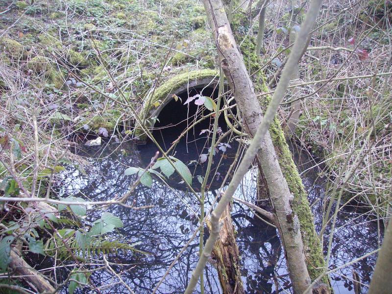
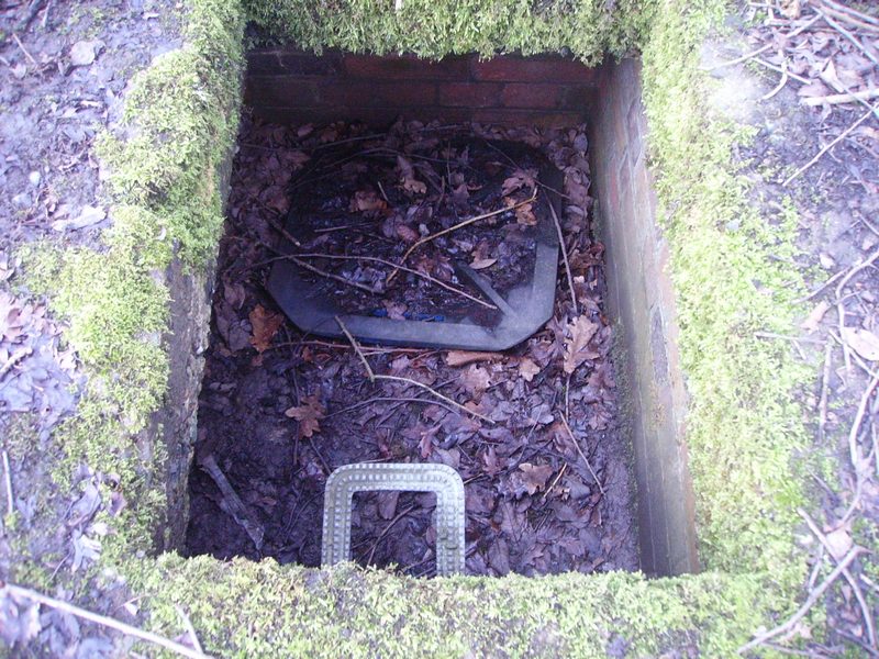
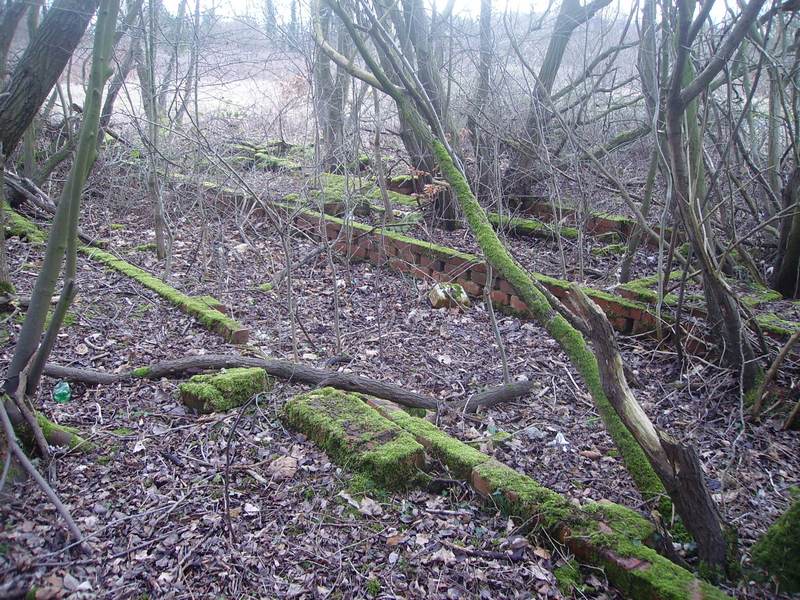
Mary Ann Site Had 2 Large Drainage Ditches & Each Drainage Ditch Had Numerous Culverts Along the Lengths of Each One Along With Many Discharge Pipes flowing into each ditch. Below is a Large Culvert Outlet Flowing East Across Mary Ann Site. This Then Flows Under Burtonwood Road & Through Mary Ann Woods.
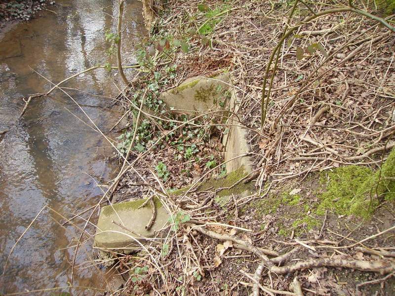
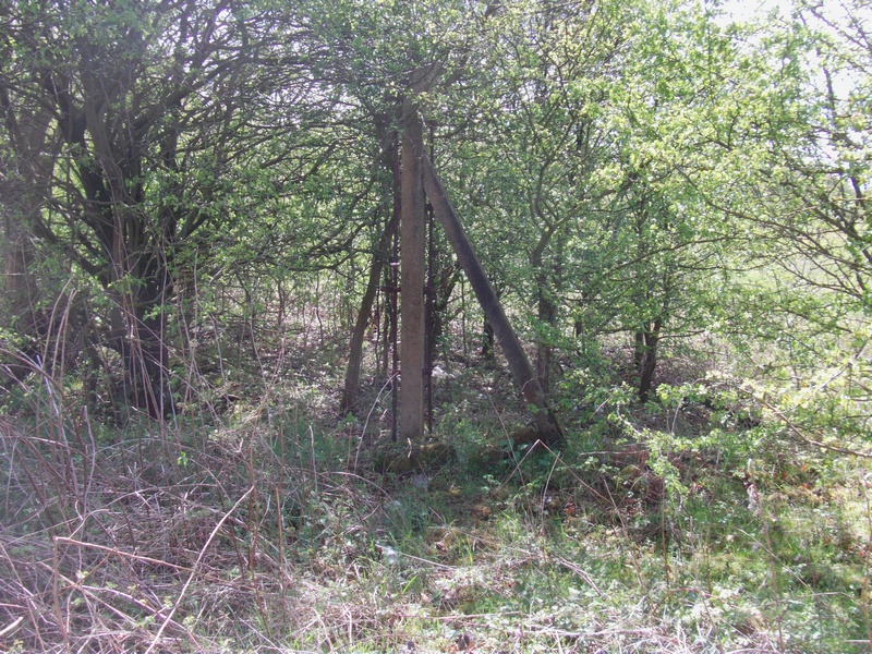
The 1st Pipe Range This 1st Pipe has Become Detached From the Opposite bank (Note the three tree branches that have grown around the steel piping)
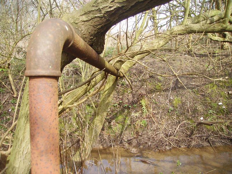
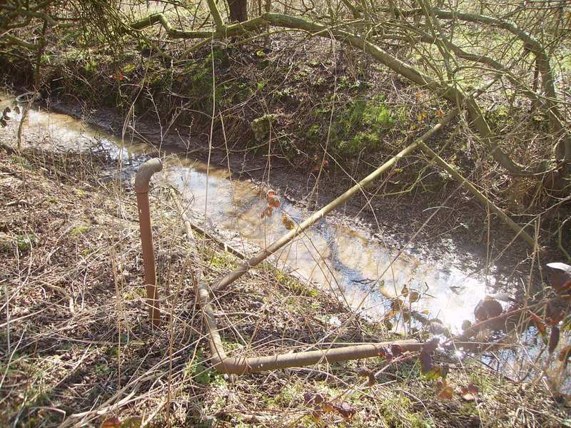
This Next Photo of The 1st Pipe Range (Taken From the Opposite Bank) Shows The Vertical Pipe Rising Out of The Ground That has Become Detached From The Pipe Crossing The Ditch
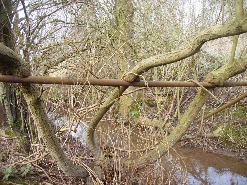
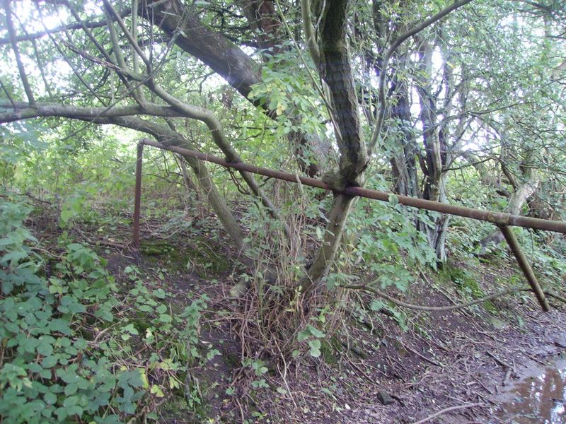
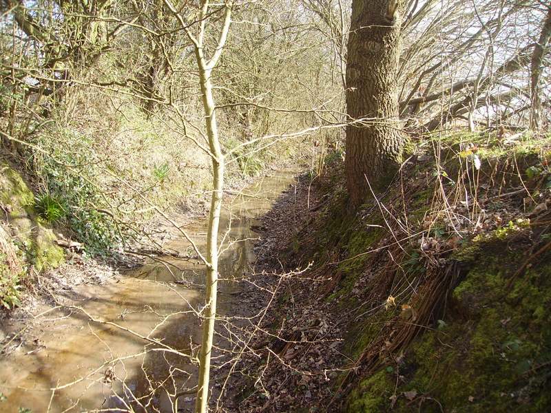
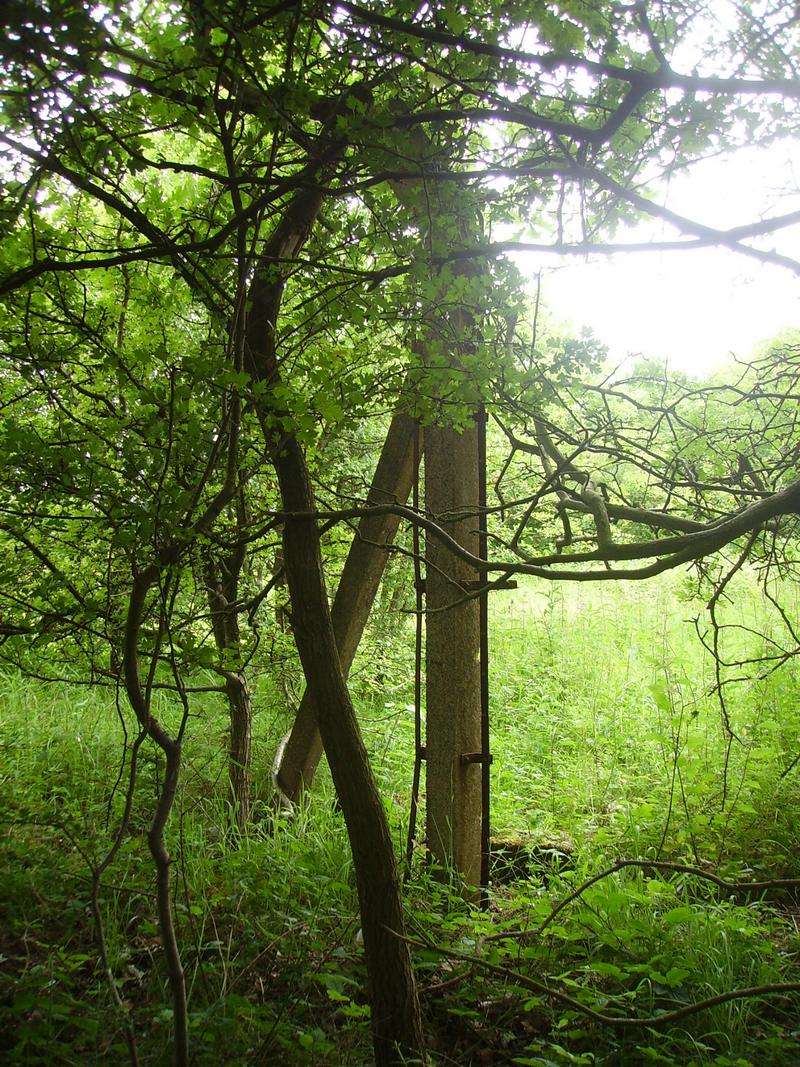
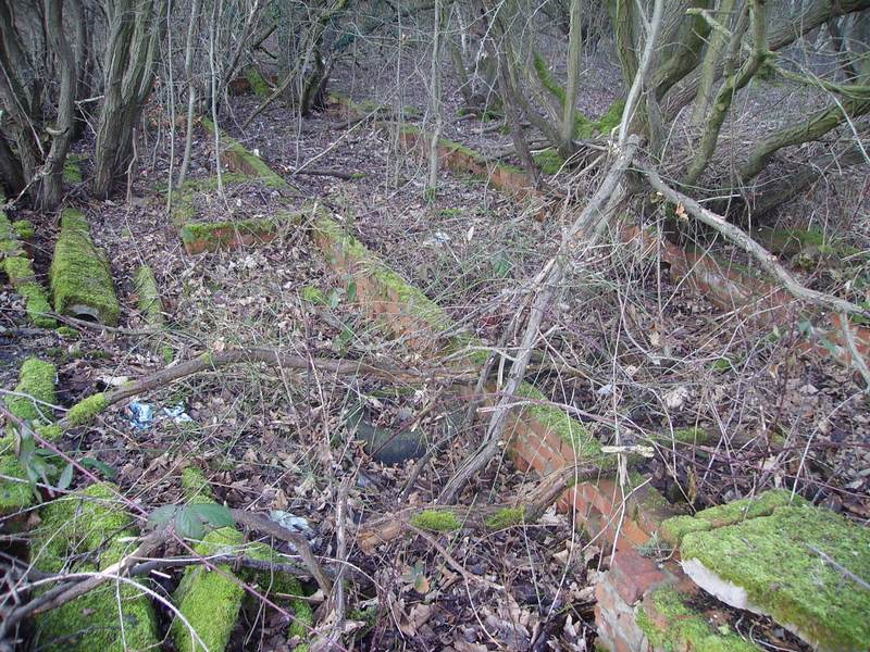
This Photo Shows The 2nd Pipe Range (lying flat on the ground going into the drainage ditch) This Pipe Also Crossed the Drainage Ditch Next to The 1st Pipe (around 3 Feet apart)
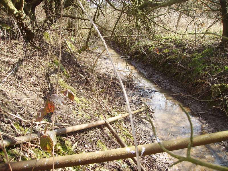
All 3 Pipe Ranges Can Be Seen From This Angle (1st Pipe Range in The Foreground, 2nd Pipe Range in the Drainage Ditch & the 3rd Pipe Range is in the Background)
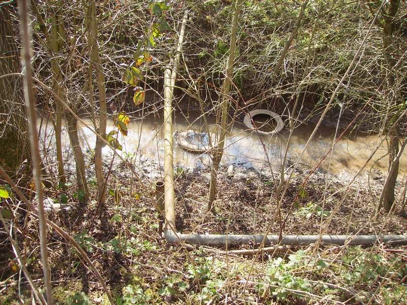
The 3rd Pipe Range This Pipe Range is the 2″ Main The Pipe Turning at a Right Angle is Following The Banking of The Drainage Ditch Towards the Large Culvert (we showed at the beginning) & Has Become Detached in Numerous Places. In the Middle of the Pipe Going Across the Drainage Ditch There is ‘T’ Pipe Fitting & This has a Discharge Pipe Directed Into The Drainage Ditch
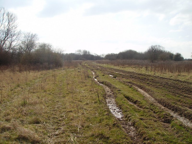
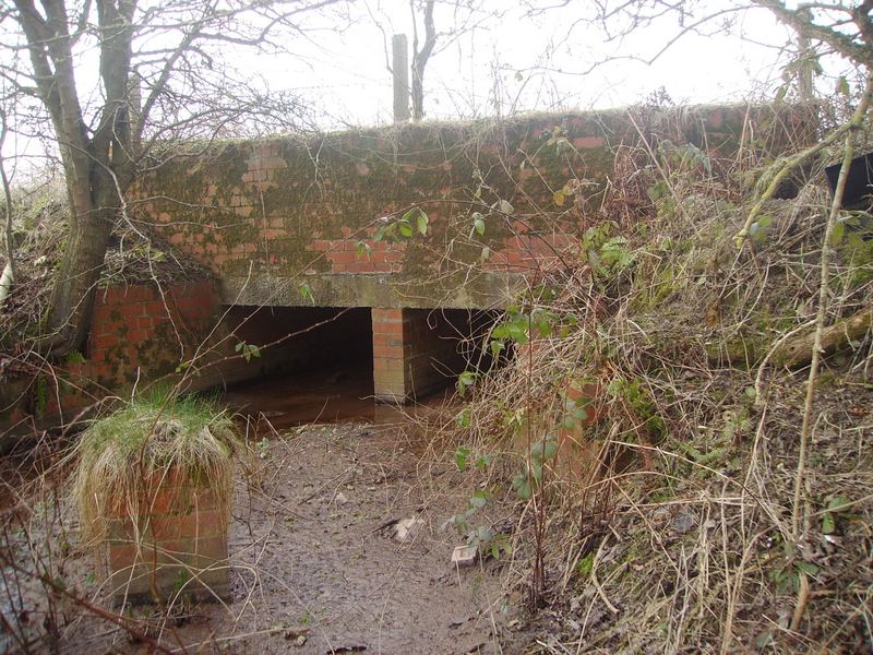
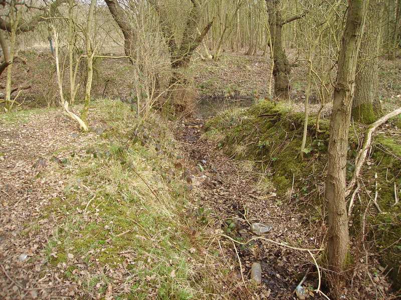
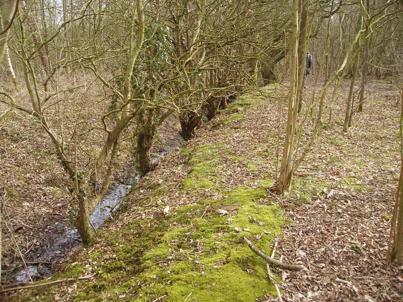
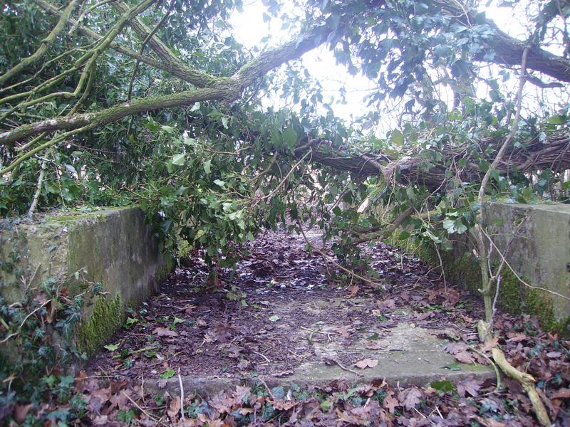
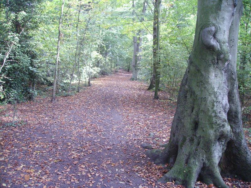
Following The Drainage Ditch Eastwards This Culvert Passes Underneath The Approach Road at the Rear of Mary Ann Site The Approach Road Was Originally a Perimeter Track to BRD Site During WW2
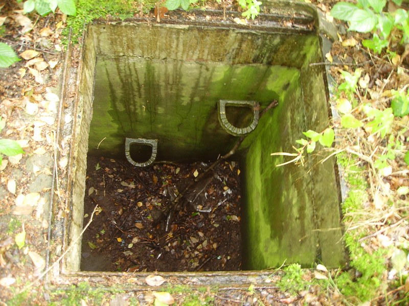
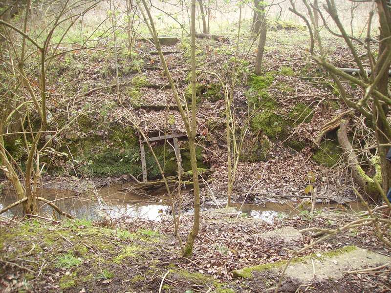
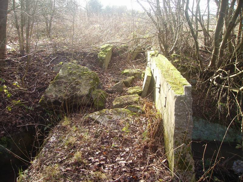
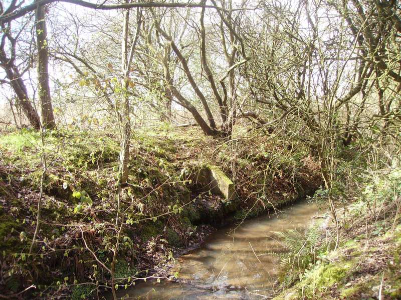
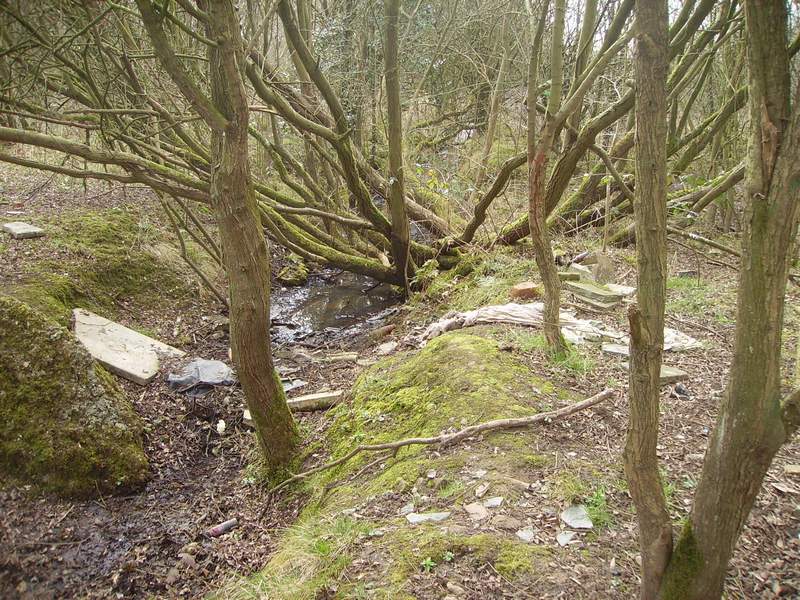
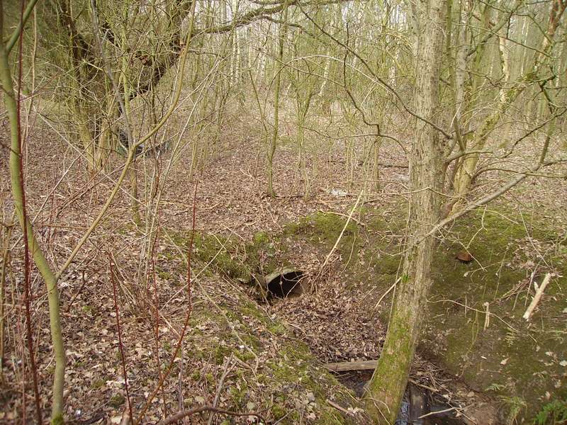
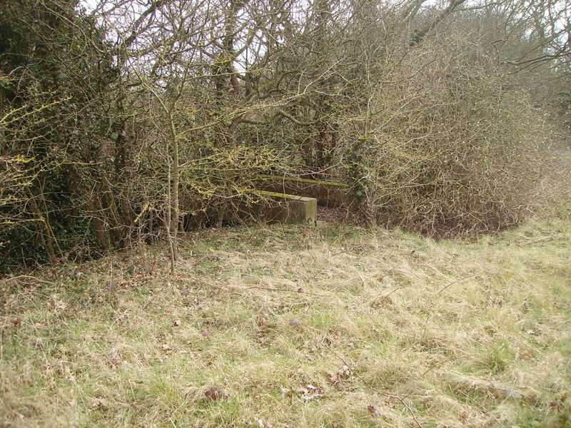
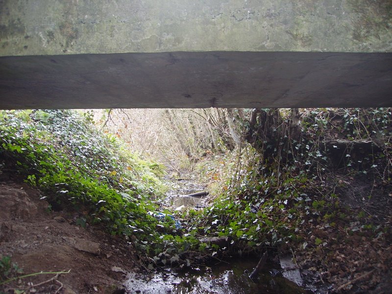
Slightly Further Along is An Older Type Pedestrian Bridge Crossing Across the Drainage Ditch with Steps Down & Up At the Bottom is the Remains of the Metal Frame Work Which Once had a Wooden Platform Located Close to the Demolished Headquarter Group Building (Building 7)
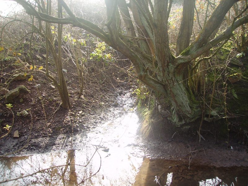
Just the the Right of the Metal Bridge is One of the Many Surface Water Drains Flowing into The Drainage Ditch
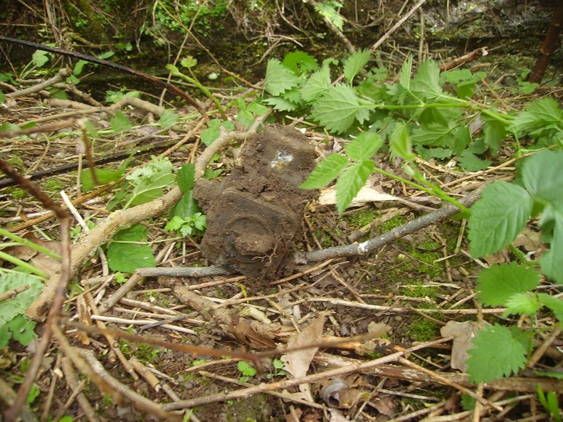
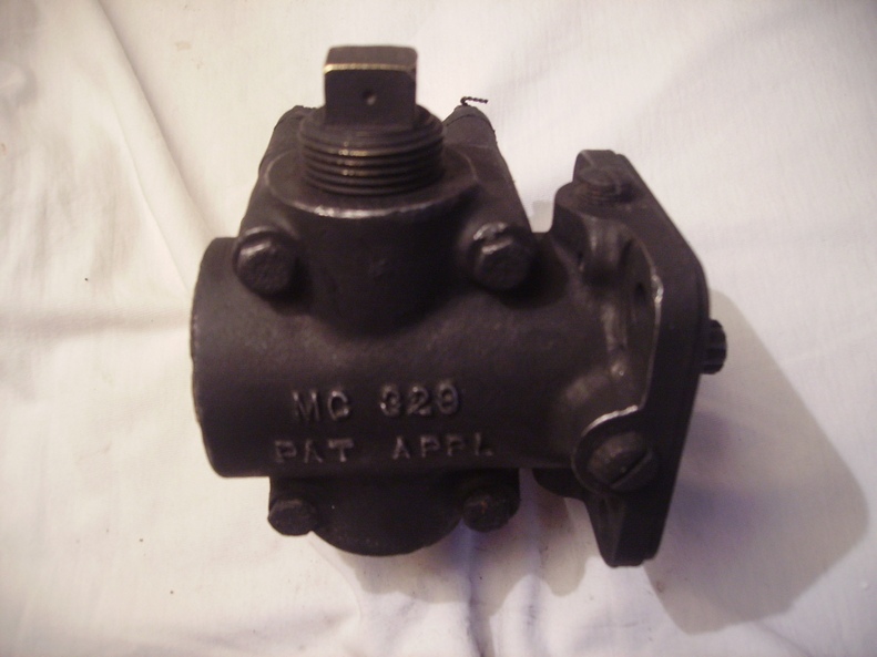
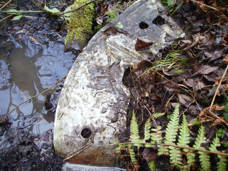
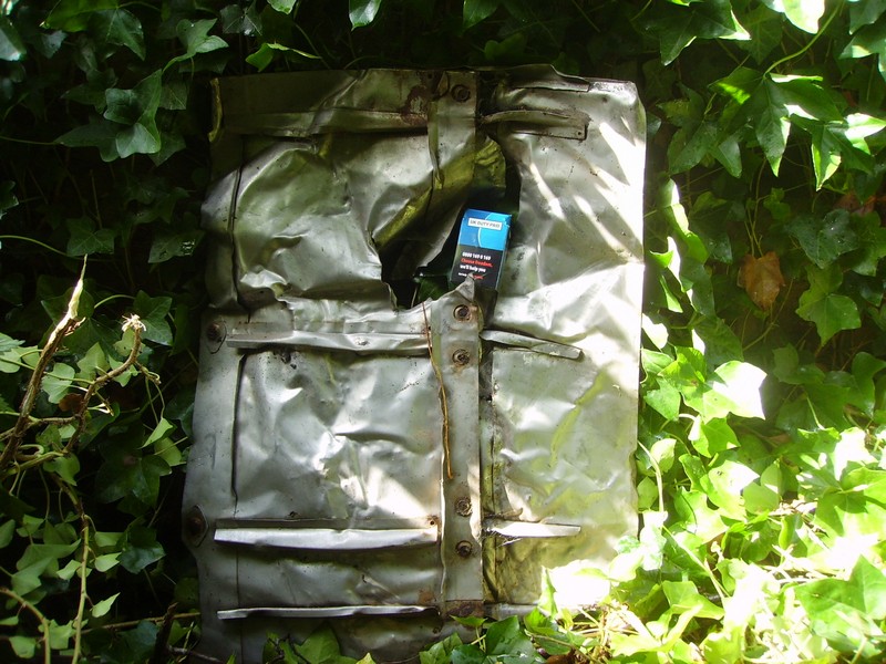
The 2nd Drainage Ditch on Mary Ann Site Flows out of a Culvert on the South East Corner Near Site 2. The Drainage ditch flows North Between Buildings 1 & 2 & Intercepts the East West Drainage Ditch next to the Approach Road Culvert. After the Culvert on the Banking of the Drainage Ditch We Found This Aircraft Engine Fuel Pump (CMC 329 GPH Aircraft Fuel Pump Designed by MC Manufacturing Company Detroit Found at Burtonwood)
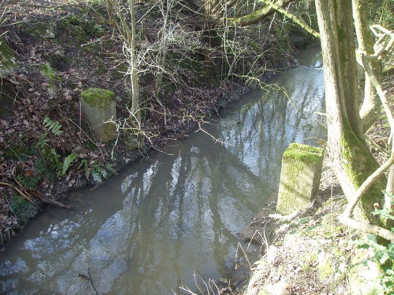
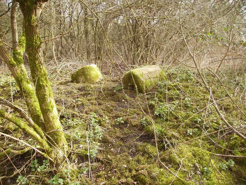
Next to the Drainage ditch are a Number of Cylinder Type Concrete Ant-Tank Obstacles. These Concrete cylinders were utilised at Road Junctions & were painted white to indicate the Road exits.
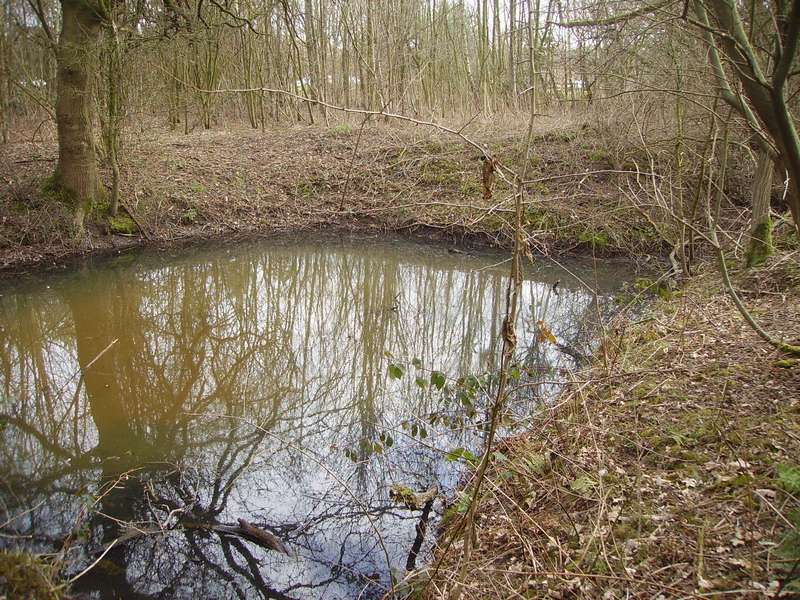
The Ditch is aligned to Keep this large Pond Full Of Water & was Probably Used as a Static Water Tank For Fire Fighting Purposes.
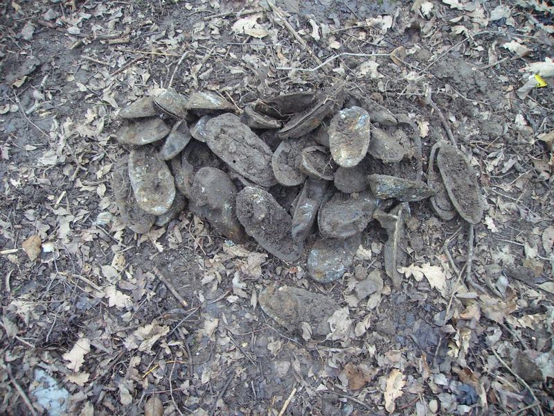
Rusting Remains (We found buried near the ditch) From WW2 Items Include: Ignition Leads, Rocker Valve Cover etc
Pierced Steel Planking The remains of pierced steel planking (below) is alongside the drainage ditch between buildings 1 & 2 warehouse workshops. (Pierced Steel Plank, or PSP Mat, was developed by the US Army Corp in anticipation of our involvement in World War II. … The PSP mat was designed with holes to reduce the weight, improve aircraft traction and facilitate drainage)
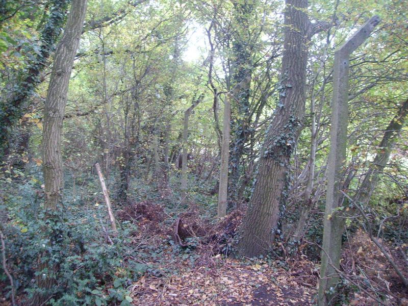
This is What Remains of the Inner Perimeter Fence Close to Where Warehouse Workshop 2 Once Stood It is Right Next to the Drainage Ditch
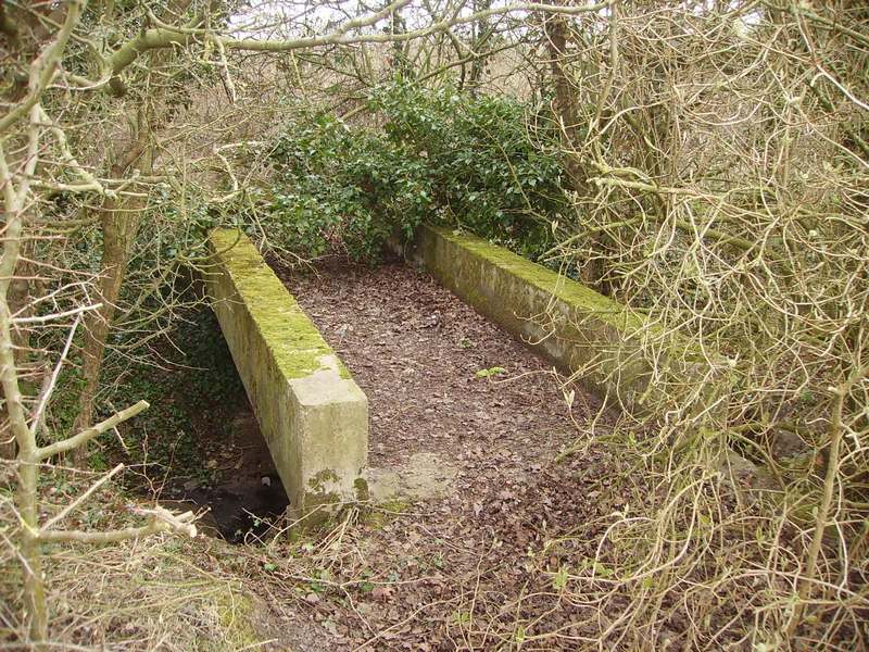
Reinforced Concrete Pedestrian Footbridge Located Next To The Front of Demolished Warehouse Building 2
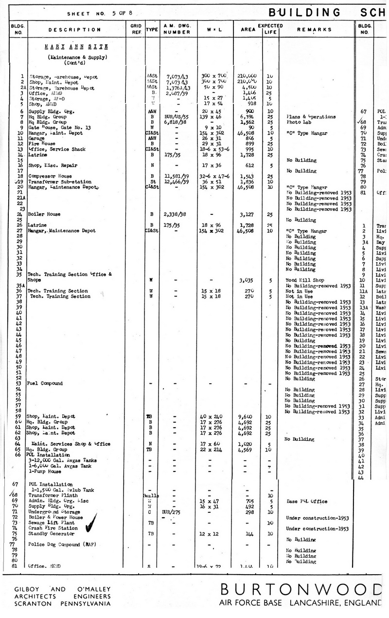
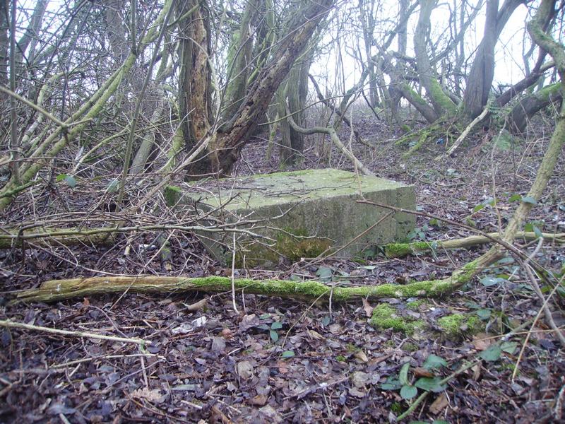
The Remains of the Foundations of Building 69. Administration Base POL (Petroleum Oil Lubricant) Office Type ‘W’ Width 15 feet x 47 feet Long Area = 705 Sq feet
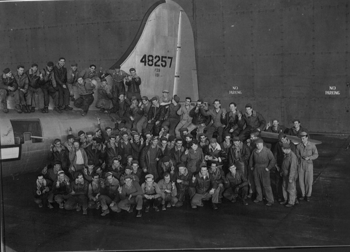
Photo outside hangar AD6 of the’DAY’shift on Mary Ann Site celebrating the 1,000th B17 through it’s doors on the 9th of September 1944. The aircraft is 48257 of the 482nd bomb group. (Note: The personnel are raising 1 finger to indicate that this aircraft was the 1,000th through hangar AD6) (Photo by Jim Varroza)
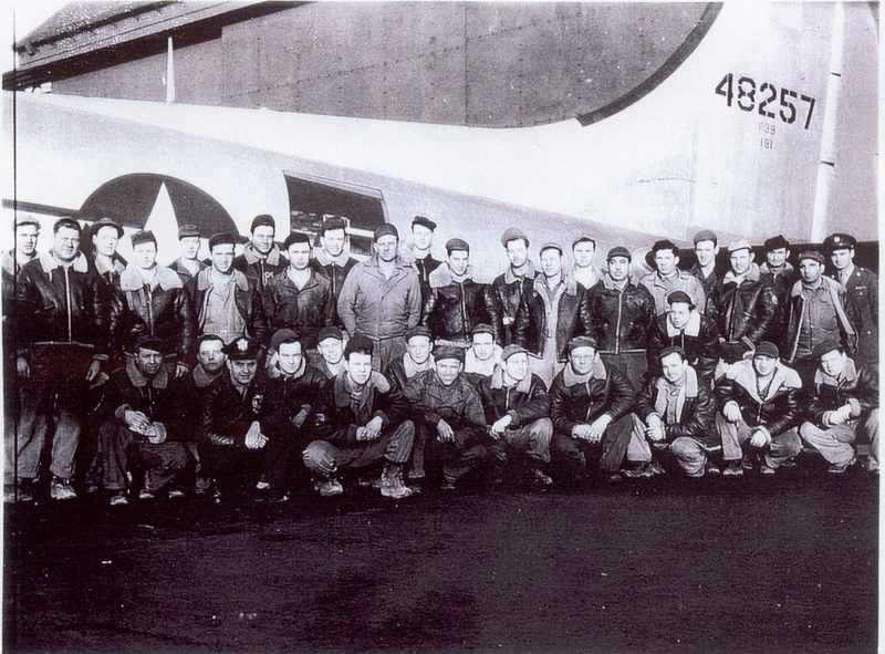
Same Photo outside hangar AD6 of the’NIGHT’shift on Mary Ann Site celebrating the 1,000th B17 through it’s doors on the 9th of September 1944.
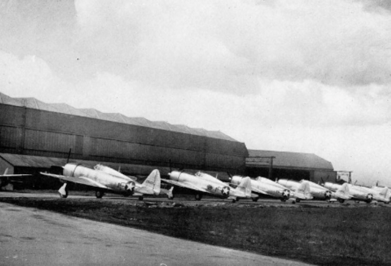
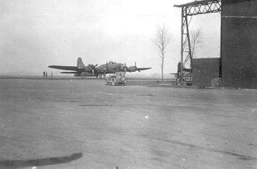
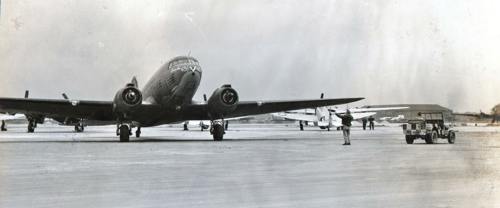
A Busy Day at Burtonwood – The Aircraft in the Foreground is a C47 In the Background You Can See 1 of the ‘C’ Type Hangars on Mary Ann Site WW2
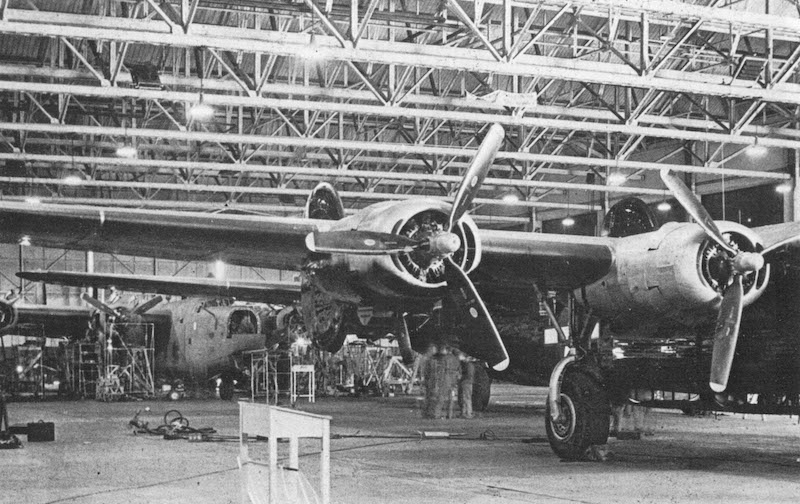
B-24 Liberator in one of the C-type hangars on Mary Ann Site Being Modified for Carpetbagger Operations. The Aircraft is Being Painted Black to Fly in Moonlit Nights and also the Ball Turret was Removed for the Dropping of Arms, Ammunition & Supplies to Resistance Fighters
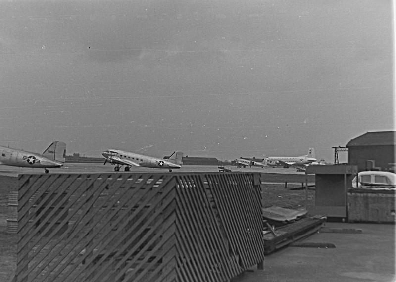
Below is a Douglas C47’s & the Large Aircraft in the Background is a Douglas C124 Globemaster Heavy Lift Transport Aircraft on Mary Ann Site Apron. ‘A’ Site can be seen in the Background with the 2 ‘K’ Type Hangars. ‘C’ Type Hangar 6 Can be Seen on the Right of the Photo Just Behind the Car. The Aircraft were operated by Military Air Transport Services.
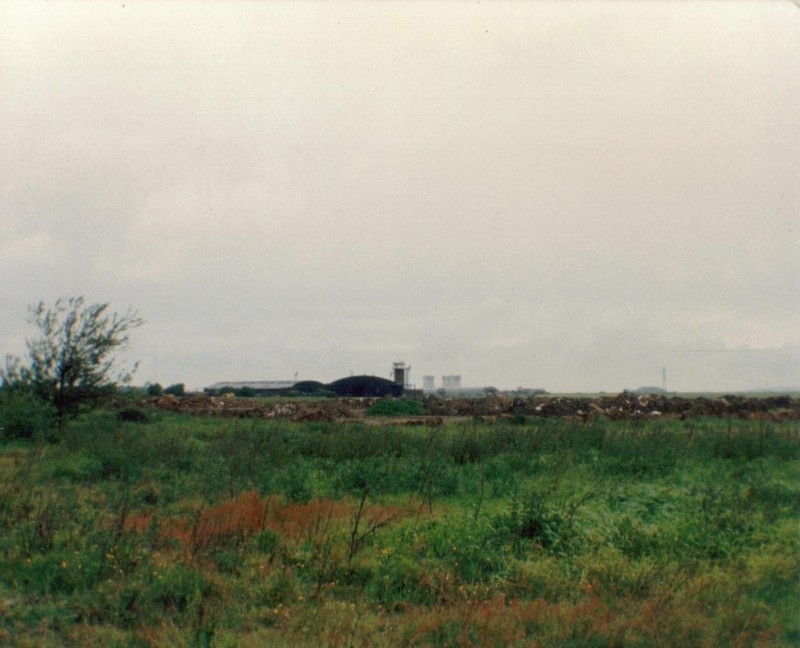
Mary Ann Site Looking Across Towards Technical Site August 1987. (Note: Bold power station in the background – now demolished)
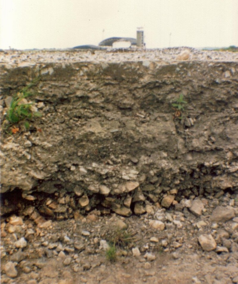
A Cross Section of the Excavated Apron on Mary Ann Site November 1987 Looking Towards Technical Site in the Process of Hangar ‘J’ Being Demolished.
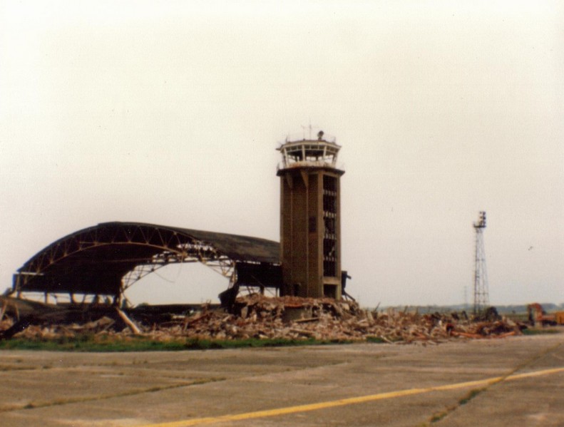
1st Control Tower WW2 1st Control Tower – to be built was a ‘Fort’ type on Mary Ann Site and this was to air ministry drawing number 207/36 concrete, as building of the airfield progressed it became apparent that the view of the main runway became obscured and therefore the 1st control tower was demolished.
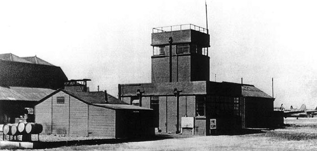
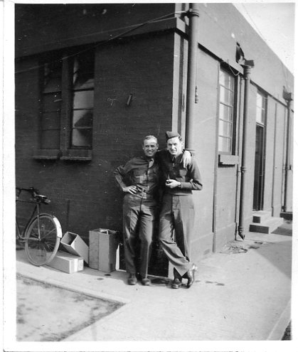
Burtonwood – Flying Control personnel – 1 May 1943 Cpl Snellinger & S Sgt Zimmerman by original control tower (Photo From The American Air Museum in Britain – Ray Zimmerman Collection via Aldon Ferguson)
Burtonwood Flying Control original control tower, 20th April 1943. L-R Pfc Roser, Pfc Demos, S/Sgt Howard Fitch (Photo From The American Air Museum in Britain – Ray Zimmerman Collection via Aldon Ferguson)
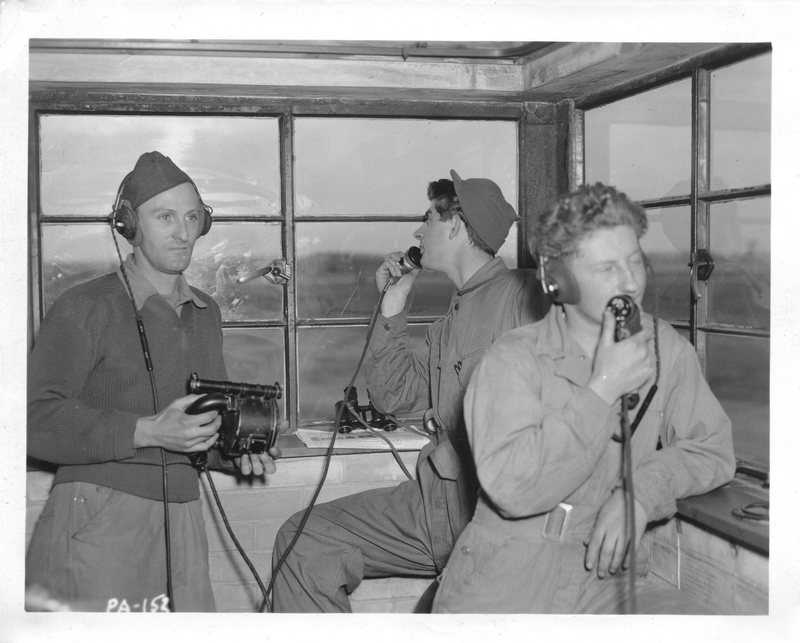
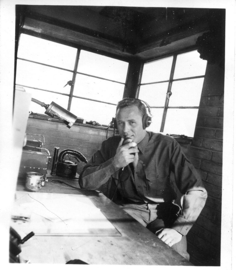
Burtonwood Flying Control 1943 inside original tower Mary Ann Site (Photo From The American Air Museum in Britain – Ray Zimmerman Collection via Aldon Ferguson)
AICMyers, AIC Orfananni & James Jones 7559th Maintenance Group 1953 James Jones in the Vehicle Production Control – 7559th Maintenance Group 1953 Miss Margaret Topping was a very kind lady who worked in the canteen at Mary Ann site for over 5 years during world war II
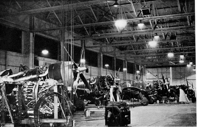
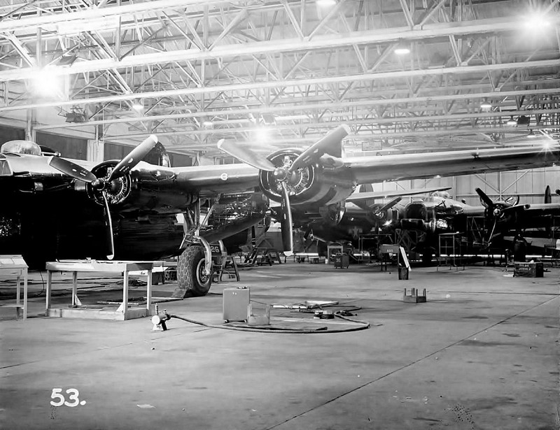
Consolidated B-24 Liberators undergoing maintenance and modification in one of the C-Type hangars at Mart Ann Site during WWII
Rest break outside building 225 supply warehouse and workshops at Mary Ann Site in WWII In the background are the chimneys of the site’s boiler house and C-Type hangar AD6
Aircraft Maintenance workers having a rest break along the side of the blast wall of hangar AD6 that they are working in at Mary Ann Site during WWII Photo credit Robert Weynand
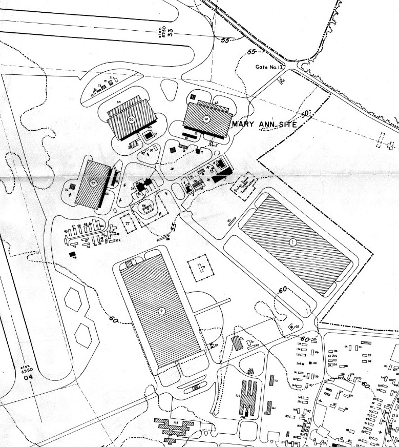
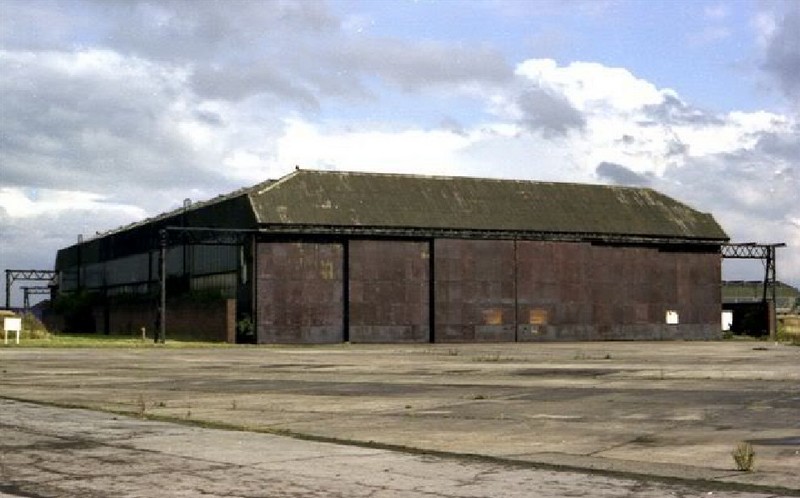
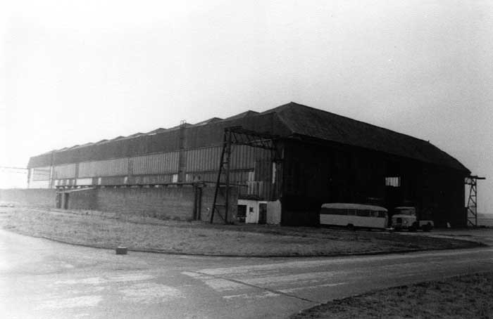
A 1947 photo of RAF Burtonwoods Mary Ann Site 3 C-Type hangars were constructed to Air Ministry Drawing numbers 8180/38 and 5533/39 The USAAF added the initial AD before the hangar numbers meaning Aircraft Dogk thus being AD4, AD5, and AD6 The length of the hangar is 300 feet and the width is 154 feet Burtonwoods C-Type hangars were of the Austerity design and had the height reduced from 35 feet to a clear height of 30 feet with an open working area of 45,000 square feet The C-Type hangars were constructed to Air Ministry Drawing numbers 8180/38 and 5533/39 Also 2 supply warehouses with workshops buildings numbered 225 and 226 were constructed to drawing number 7,073/43 They were built With a width of 300 feet and length of 700 feet and a floor area of 210,000 square feet
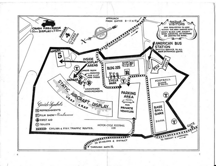
Below is a plan (from out of the programme) of Armed Forces Day on Mary Ann Site on the 17th of May 1958.
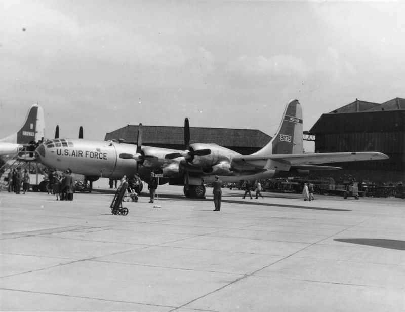
Boeing WB-50 9275 of the 53rd Weather Reconnaissance Squadron at the Open Day on the 19th of May 1956 on Mary Ann Site with Type ‘C’ Hangars in the Background. AD5 is on the Left in the Background & AD6 is on the Right. The 53rd Weather Reconnaissance Squadron was a Resident Unit at Burtonwood & Maintained & Operated their Aircraft From Mary Ann Site (These Hangars Above)
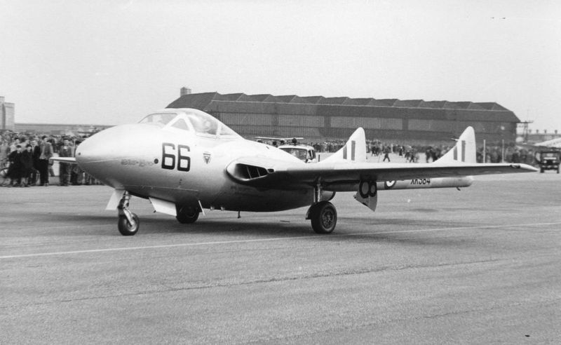
FTS Vampire T.11 XK584 66 17th of May 1958 open day. (Please note the distinctive multi pitched roof of one of the ‘C’ Type hangars can clearly be seen on this photo below)
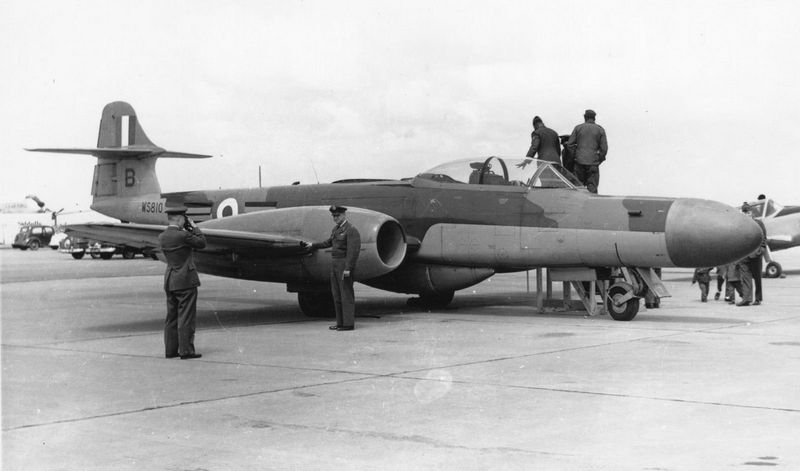
Meteor of 264 Squadron NF.14.WS810B Open House May the 18th 1957
© Historic Aviation Military — All rights reserved Non Commercial — Non Profit Website / Organisation