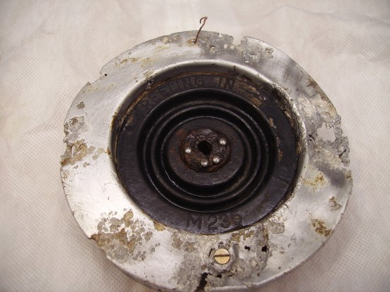
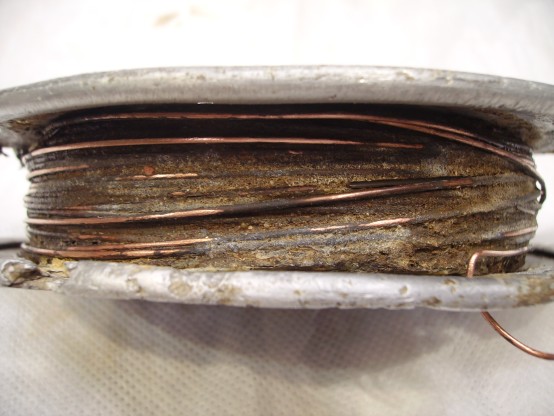
Aircraft Findings Bendix Scintilla Aircraft Magneto Found in a Warrington Scrapyard Near RAF Burtonwood.
The Side of The Magneto Showing The Output Cables on The Top Left & The Contact Point’s on The Bottom Right.
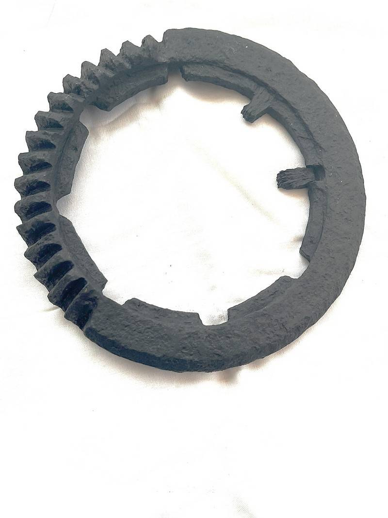
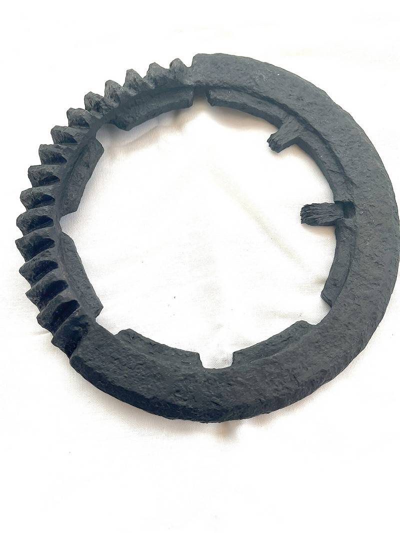
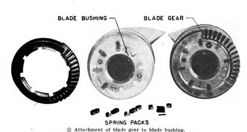
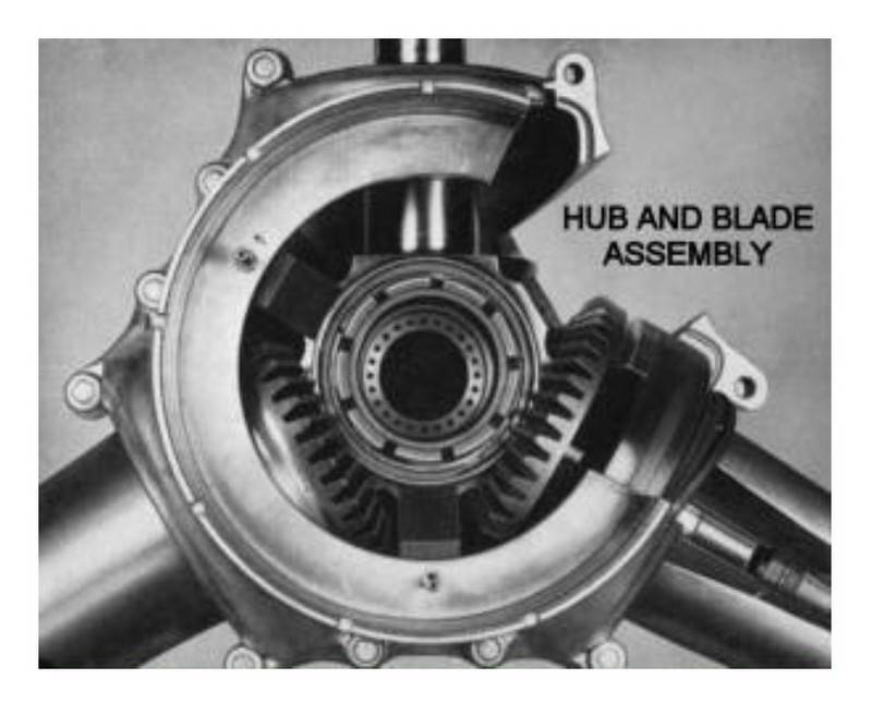
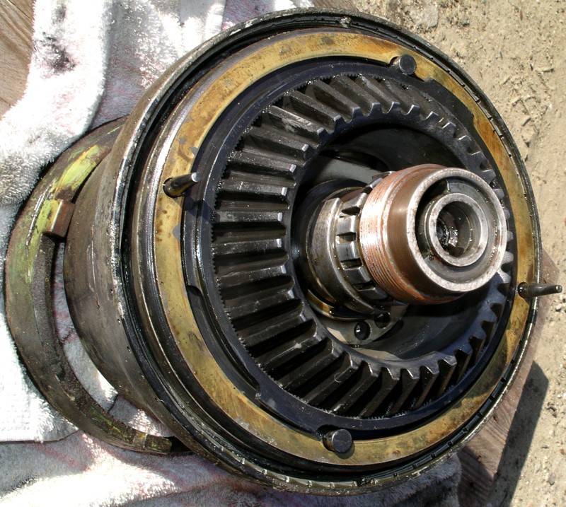
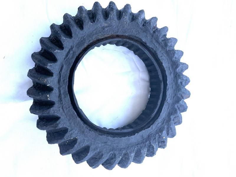
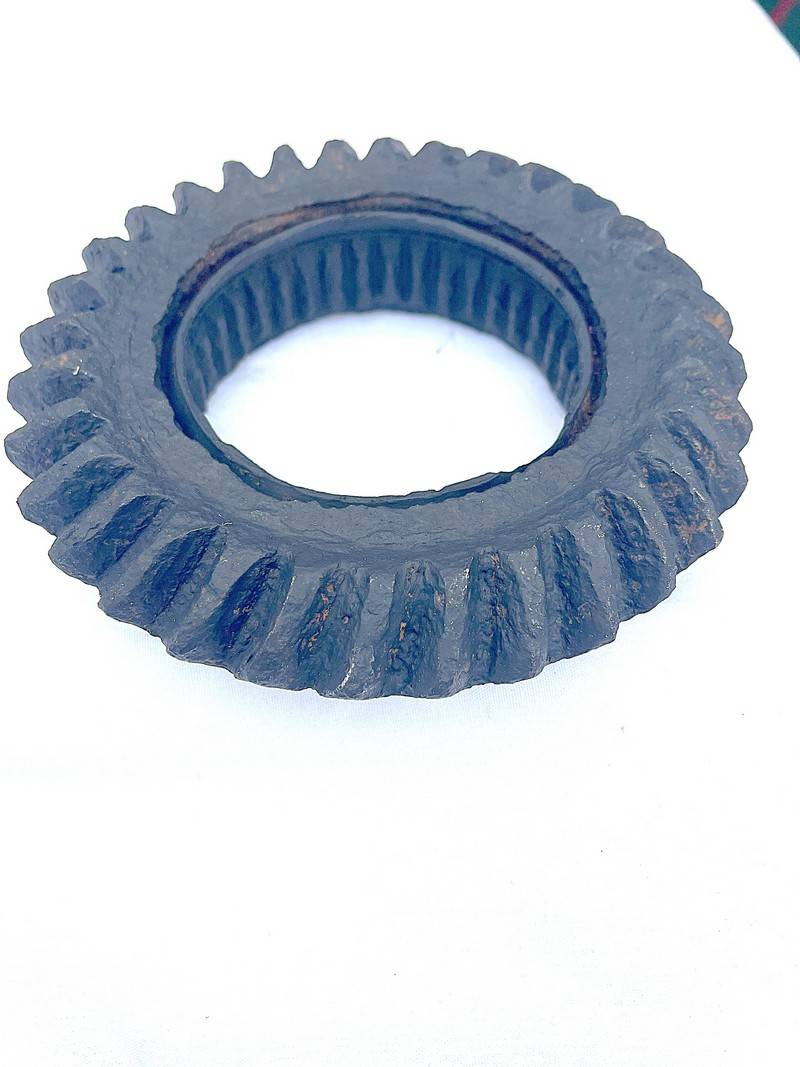
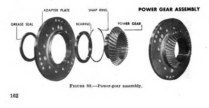
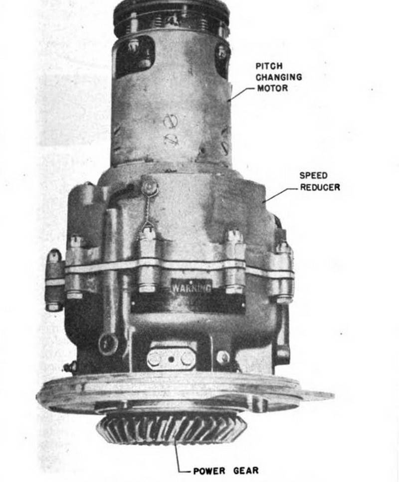
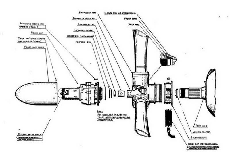
Found on the Mary Ann Site at RAF Burtonwood is a Hamilton Standard Propeller blade gear segment and a Curtiss power gear
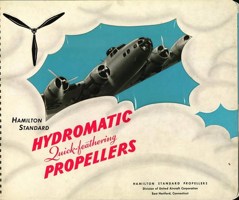
Hamilton Standard became the primary propeller manufacturer for the Allies during World War II. Virtually the entire front-line inventory, from multi-engine bombers to fighter and transport aircraft, as well as a significant majority of RAF aircraft, employed Hydromatic propellers. Hamilton Standard and its three licensees–refrigerator manufacturers Frigidaire and Nash-Kelvinator, and office equipment maker Remington-Rand–produced 530,135 Hydromatic propeller assemblies during the war. Vintage advertisement for Hamilton Standard Hydromatic Quick-feathering Propellers.
The Hamilton Standard propeller blade gear segment located at Burtonwood is driven by a rotating cam, which is actuated by a hydraulic piston inside the propeller hub. The piston’s forward or aft movement, controlled by the governor and engine oil pressure, causes the cam to rotate clockwise or counter-clockwise, respectively, thereby turning the blade gears and changing the blade angle (pitch).
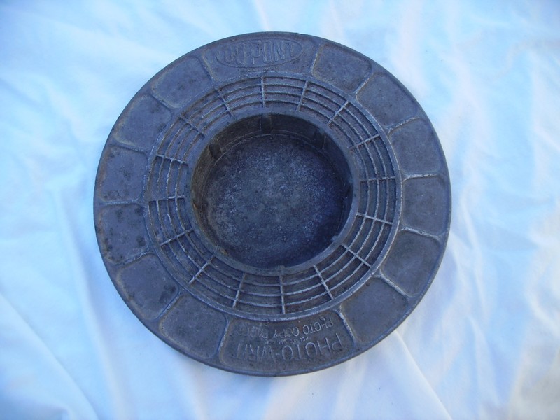
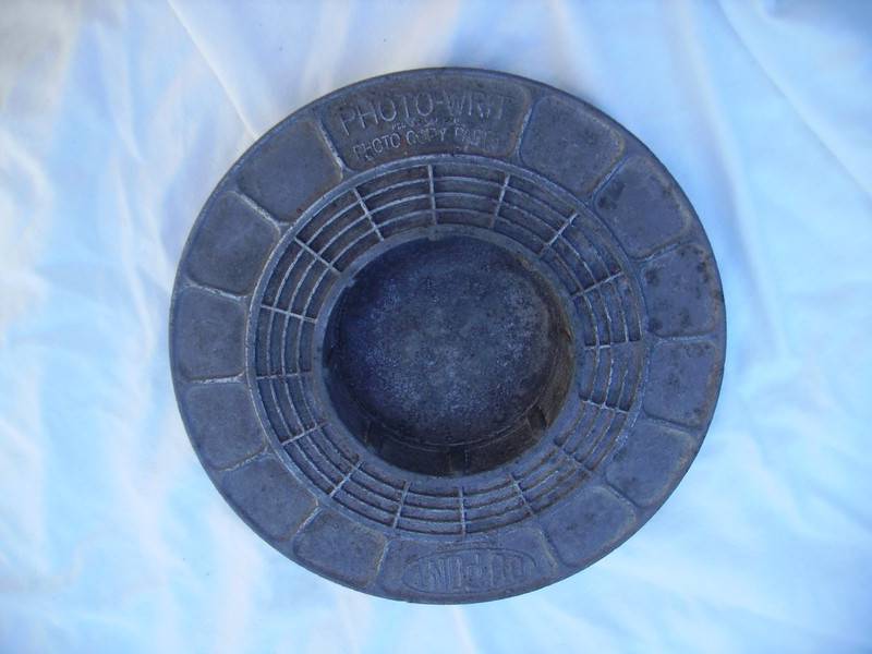
Made of metal by the Dupont Corporation. This ash tray/change dish advertisesthe photo writ photocopy paper.Dimensions: 6.5″ diameter x 1″ high.Weight: 9.2 Oz.
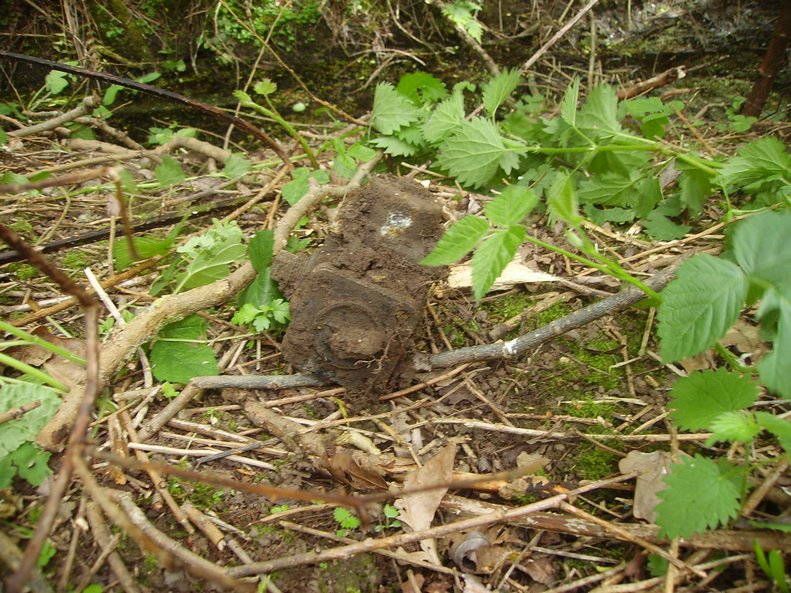
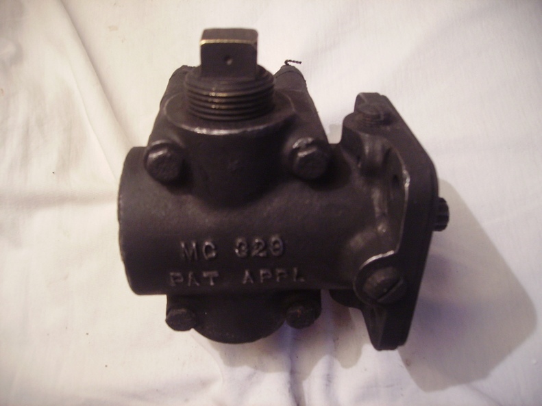
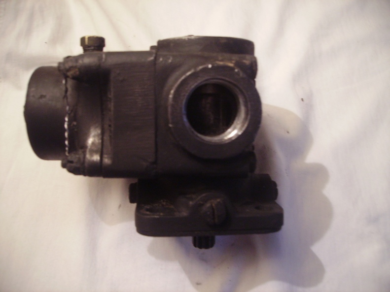
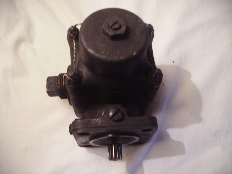
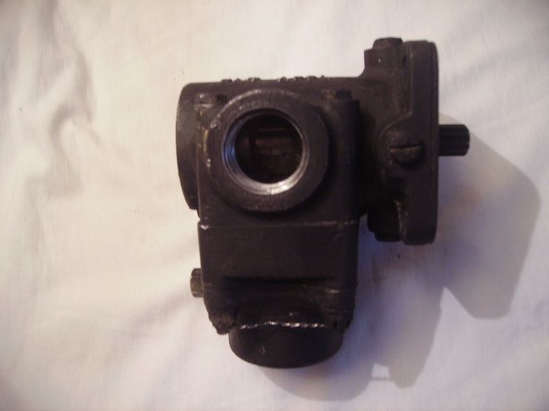
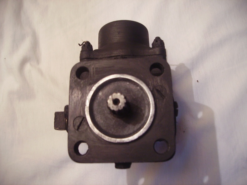
CMC 329 GPH Aircraft Fuel Pump Designed by MC Manufacturing Company Detroit Found at Burtonwood 10th of May 2015
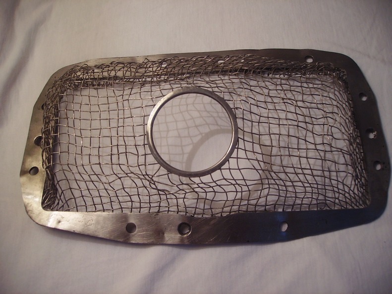
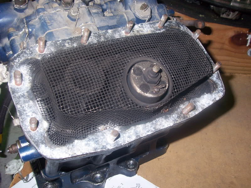
It’s a filter from a Bendix Stromberg PD-12H2 carburettor, as fitted to Wright Cyclone R-1820-97 engines on B-17s.
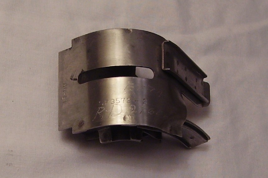
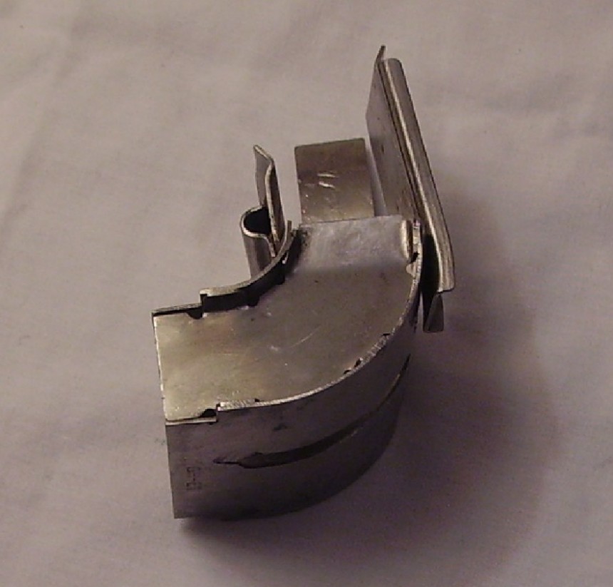
Concur, link ejection chute from a .50 cal aircraft machine gun manufactured in this case by Emerson. Part Found at Burtonwood 5th of October 2014? There are a variety of numbers engraved and stamped on this item. There is: GR-ET SP 3572 – 2 RD24606 ET740E Thanks again to Paul Bellamy for the Info.
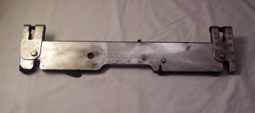
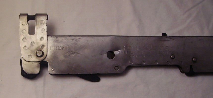
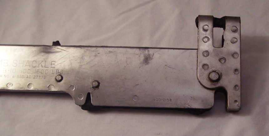
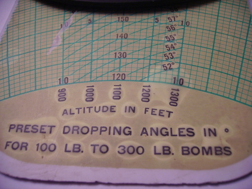
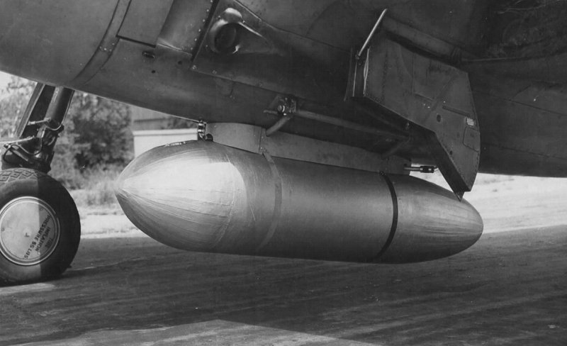
Type AN-B-10 100- 1600 Lb’s Bomb Shackle Found at Burtonwood 5th of October 2014 The bomb shackle was clipped to a bomb and then installed in the bomb bay. The shackle held the bomb in the rack and was tripped by an electrical release unit to drop the bomb. The shackle remained on the aircraft and was re-used.
The following numbers can clearly be seen on the bomb shackle on this image below: Order Number W-535-AC-27778 (on the left hand side) 43D10158 (on the right hand side lower down)
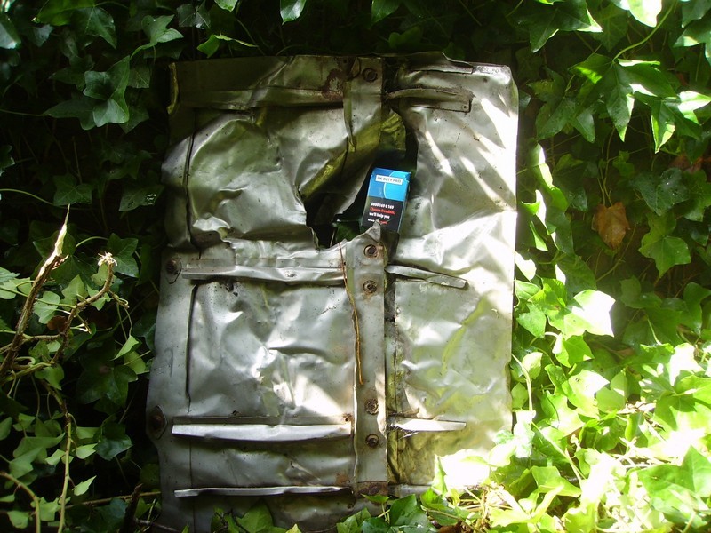
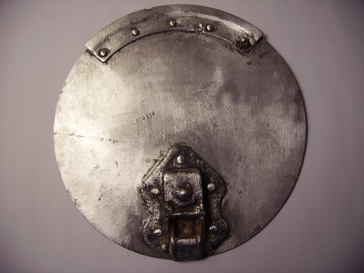
Updated 30th of March 2014 Fuel Tank Filler Port (flap) Cover (inside) Found on the 30th of March 2014 at Burtonwood part number: 4138119 (546 is also above that number) Any ideas of which aircraft this is from?
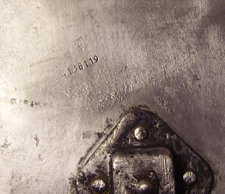
Close up View of Above Fuel Tank Filler Port (flap) Cover (inside) part number: 4138119 (546 is also above that number in a sort of square shape) Any ideas of which aircraft this is from?
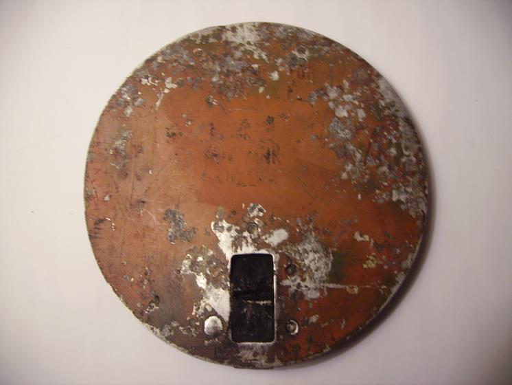
Fuel Tank Filler Port (flap) Cover (outside) Found on the 30th of March 2014 at Burtonwood There is some writing in ink on this but we cannot make it out clearly? It looks like it says: ‘Fuel Tank Filler’ Any ideas of which aircraft this is from?
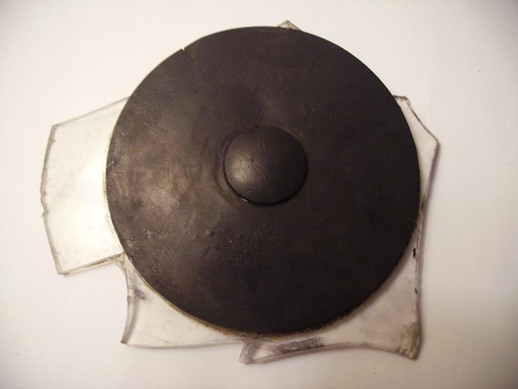
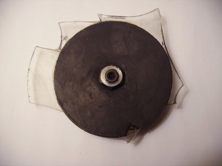
Side 1 of a Slightly Rounded Black 4″ Disk – Bolted to Plexiglass Found on the 30th of March 2014 at Burtonwood
Side 2 of a Slightly Rounded Black 4″ Disk – Bolted to Plexiglass Found on the 30th of March 2014 at Burtonwood This part is built into the roof of the navigators astrodome. The centre metal has an inside thread to support the weight of a navigators sextent. This was sometimes used because the sextent was quite heavy to hold.
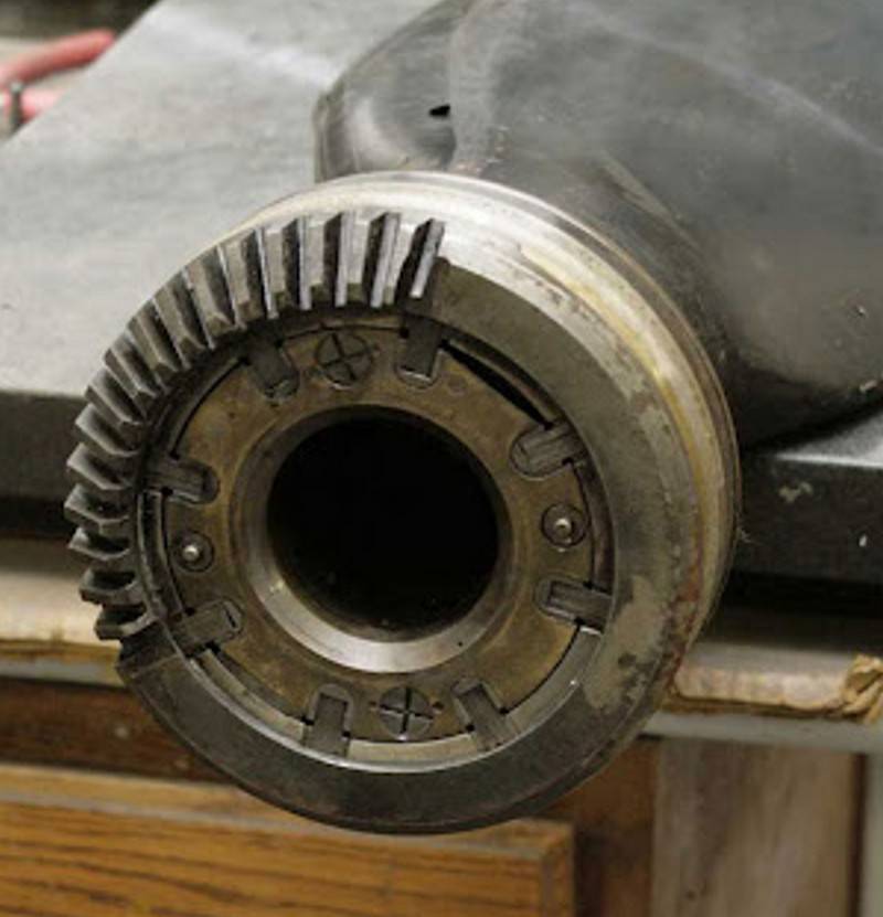
Propeller Barrel Assembly Housing Found on the 23rd of March 2014 at Burtonwood Any ideas of which aircraft this is from?
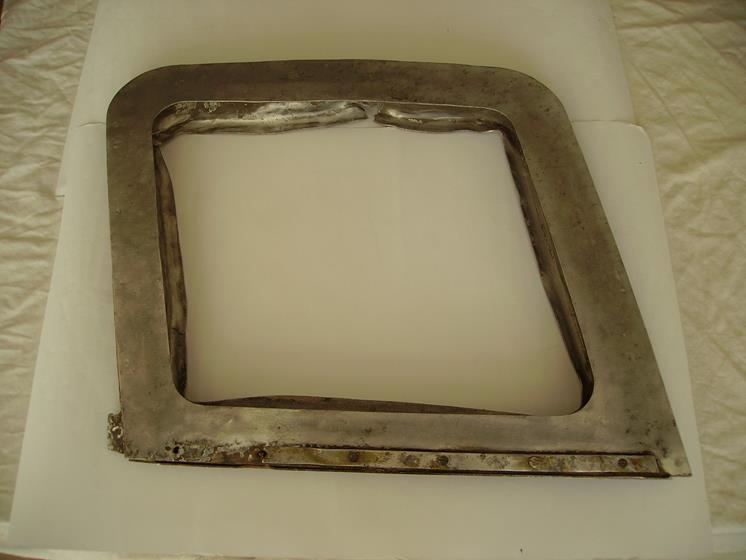
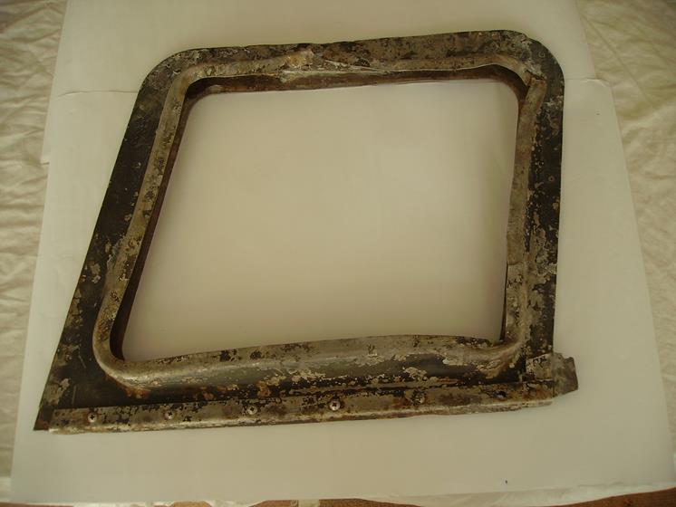
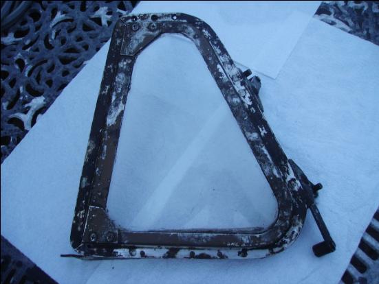
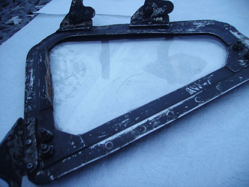
Window Frame Found on the 23rd of March 2014 at Burtonwood The part number in a circle is 138 Any ideas of which aircraft this is from?
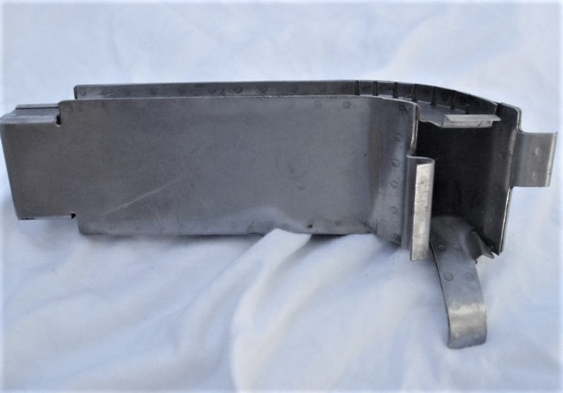
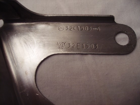
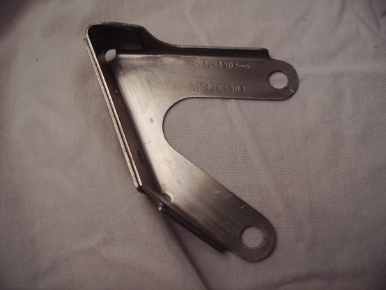
Photo Below is a Bracket Part. (Found at Burtonwood Today 18th of August 2013) The Part Numbers Stamped On it are: 24 (in a circle) 32E1503-6 Assembly Number 32E1503 Faint ink stamp with date May 25th 1944 Faint Number is 195 Thanks to Paul Bellamy For Identifying the part as: 32E1503-6 32= B-24 Liberator E = Electrical system Other than that, it’s the 6th part of sub-assembly 1503
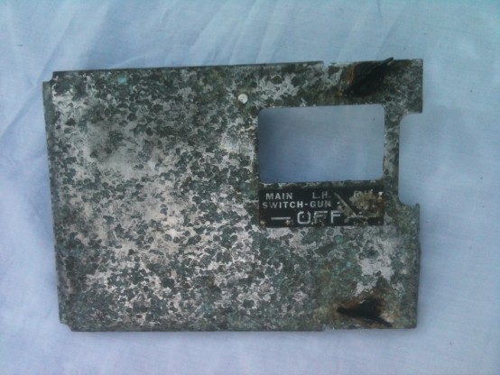
Photo Below is a Main Switch Cover. It is a Main Switch For ‘Gun Off’ Left Hand & Right Hand ‘Gun Off’. The Part Numbers Stamped On it On The Reverse Side Are: T1283 AM J27
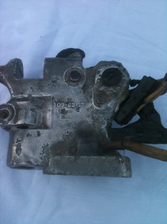
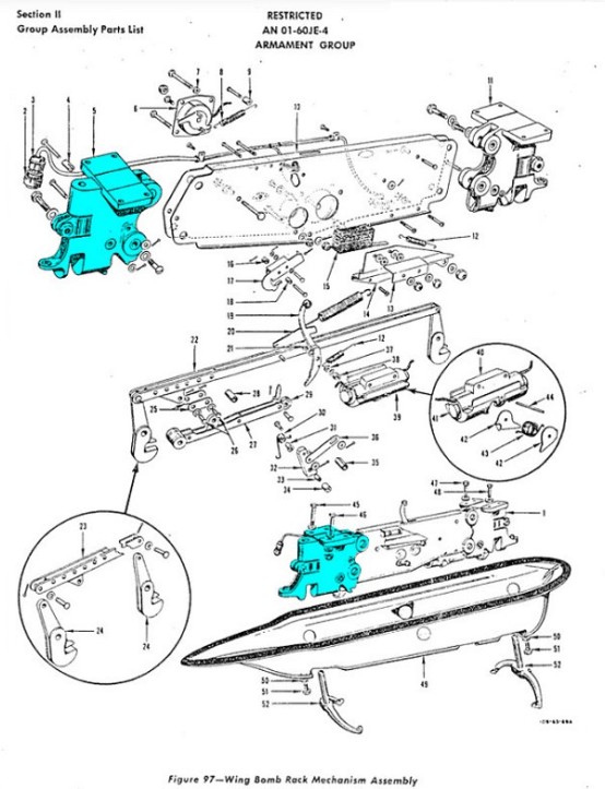
P-51 Mustang Wing Bomb Rack The Part Numbers Stamped On it Are: 109-63117 AN D78 (In a Circle) Part numbers prefixed 109 are originally for the P-51D. The casting is a bit corroded, so the number is 109-63117: Support Assembly, Wing Bomb Rack, Rear, Left Hand. Component part of 109-63218: Mechanism Assembly, Bomb Rack, LH. (Thanks again to Paul Bellamy for his help finding out what this item was for and which aircraft it was fitted on as well)
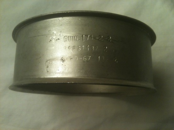
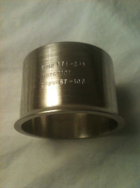
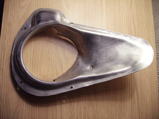
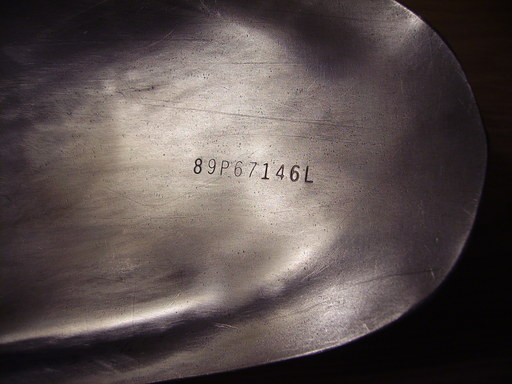
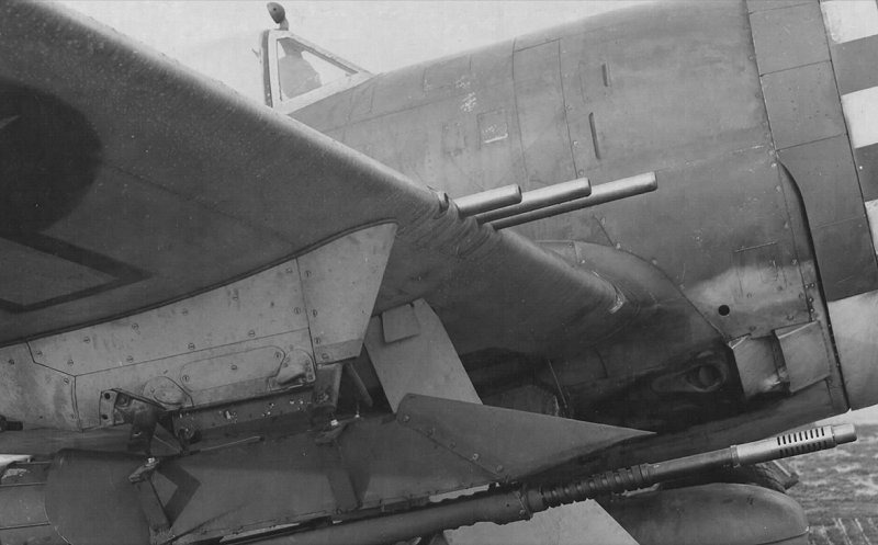
Photo Below is Part of The Exhaust System From a P-47 Thunderbolt. The Part Numbers Stamped On it Are: BUHL 171-2-9 89P67107 C-89-67-107 We can’t find item 89P67107 specifically listed anywhere but, as noted above, the 89P67xxx number means it also has to be part of a P47 exhaust system. Found at Burtonwood 23rd of June 2013. (Thanks again to Paul Bellamy for his help finding out what this item was for and which aircraft it was fitted on as well)
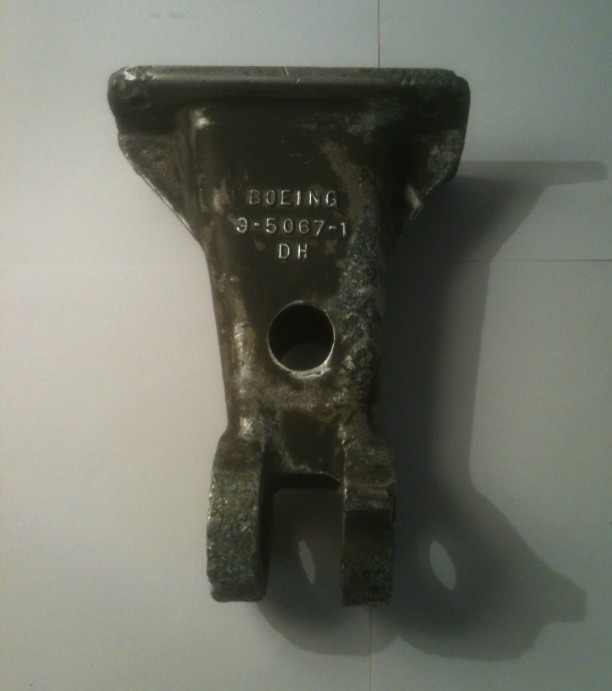
Photo Below is a Casting Support Rudder Trim Tab Control From a B-17 Boeing 9-5067-1 DH Found at Burtonwood 16th of June 2013. (Thanks again to Paul Bellamy for his help finding out what this item was for and which aircraft it was fitted on as well)
Aircraft Aluminium P47 Supercharger Wastegate Shroud, With Part Number Visible As Shown in Photos. Found at Burtonwood 26th of May 2013. The bulge at the top is to clear the flap operating mechanism, so the post and starboard shrouds are mirror images. Please Note: This one is a starboard one (Right Side) and we found another one of these in 2012 & not far from this newer one, although that one was a portside one (Left Side). More info on the portside one can be found on this page further down.
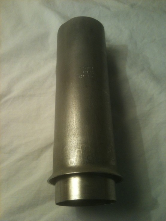
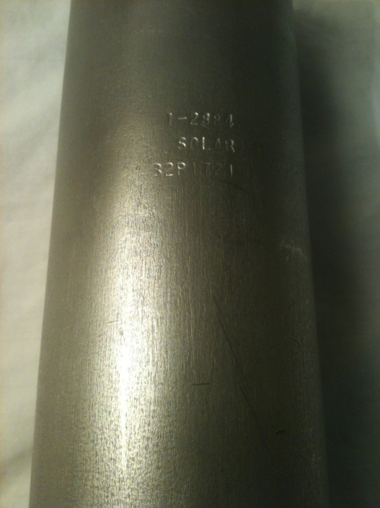
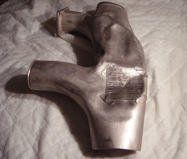
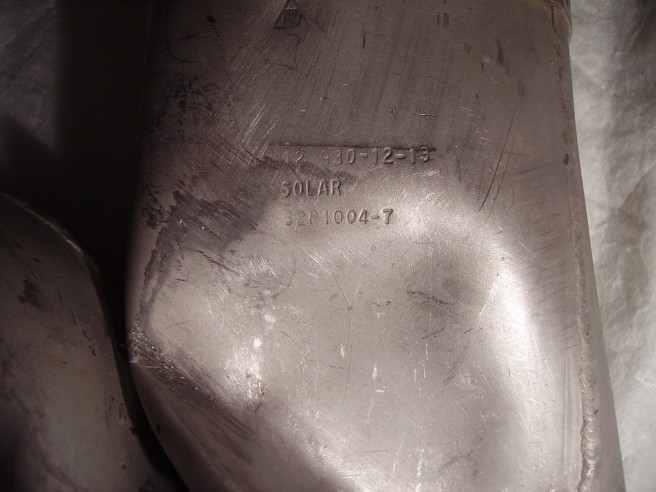
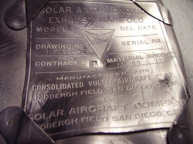
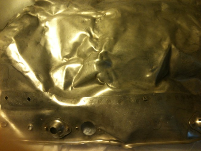
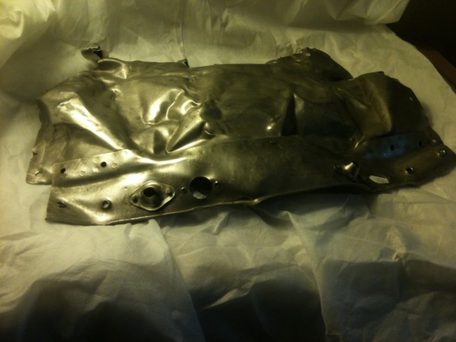
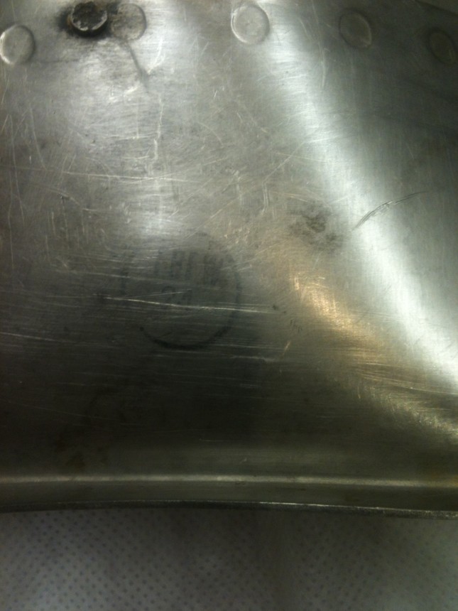
We Think That This Might Be an Exhaust Manifold From a B-24 Liberator? If you think differently then email us at: [email protected] Part Number (stamped in ink in a circle) is: 19 The other serial numbers are: 12 930-12-13 Solar 32P1004-7 And on the large manufacturers label other numbers & manufacturers info can easily be seen on the 3rd photo. Found at Burtonwood on the 14th of October 2012.
Does Anyone Know What Aircraft This is From? If you do then email us at: [email protected] Part Number (stamped in ink in a circle) is: FBFW 24 Found at Burtonwood on the 9th of September 2012.
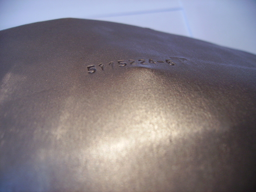
Yet Another Exhaust Manifold: Part Number is: 5115224-6 5115224-6 is the part number for an exhaust collector ring segment for a Pratt & Whitney R-1830 Twin Wasp, particularly for the C-47 and C-119 installations. (Thanks again to Paul Bellamy for his help finding out what this item was for and which aircraft it was fitted on as well) Found at Burtonwood on the 12th of August 2012.
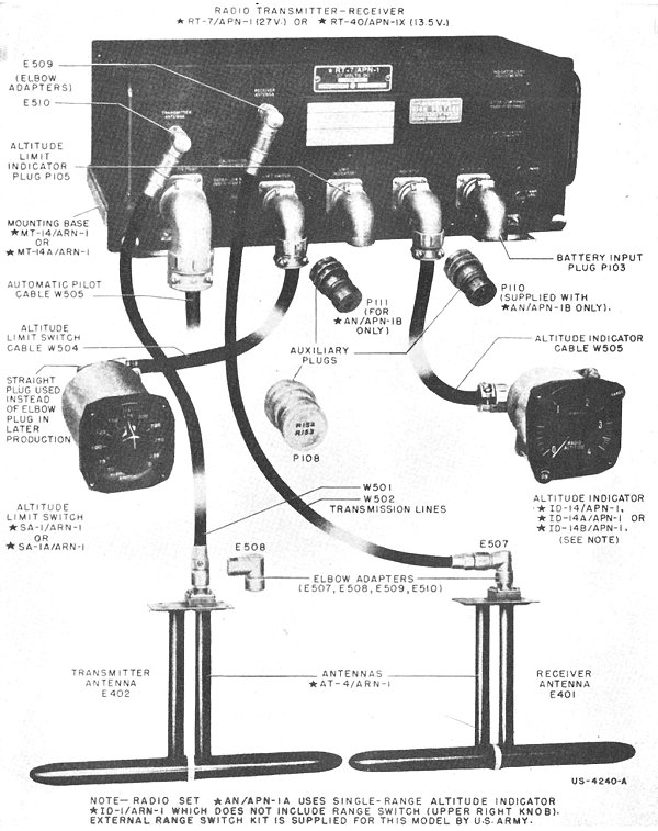
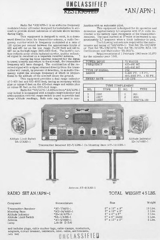
Frontplate of an RT-1/APN-1 Transceiver Part of the AN/APN-1 Radio (Radar) Altimeter system: Found at Burtonwood on the 22nd of April 2012. Thanks to Paul Bellamy Regarding The Research of Most of The Items on This Page.
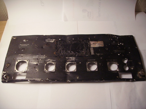
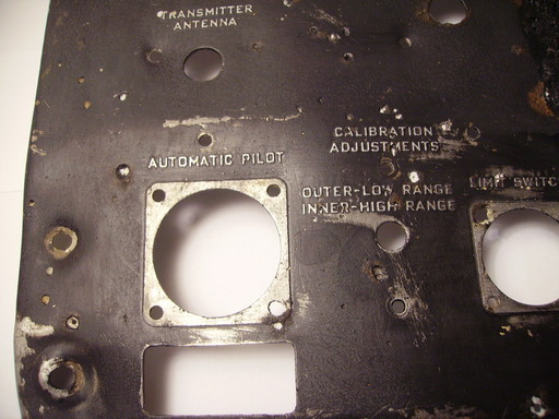
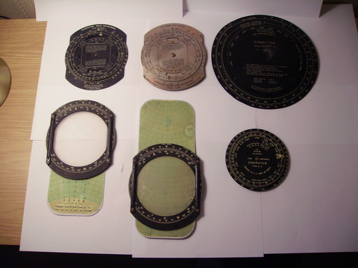
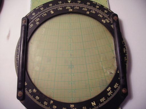
Page Updated 1st April 2012 Group Picture of Our Latest Finds (1st April) at Burtonwood USAAF Base. Navigators Instruments All Found Together at Burtonwood. Please note: We Found Many More Than These But Some of Them Have Parts Missing or Are Slightly Damaged. Found at Burtonwood on the 1st of April 2012.
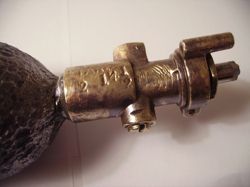
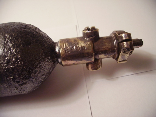
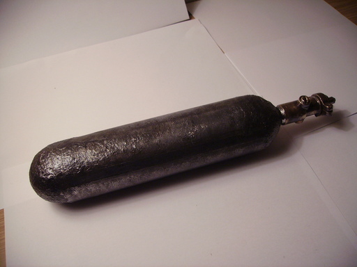
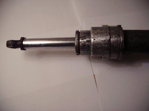
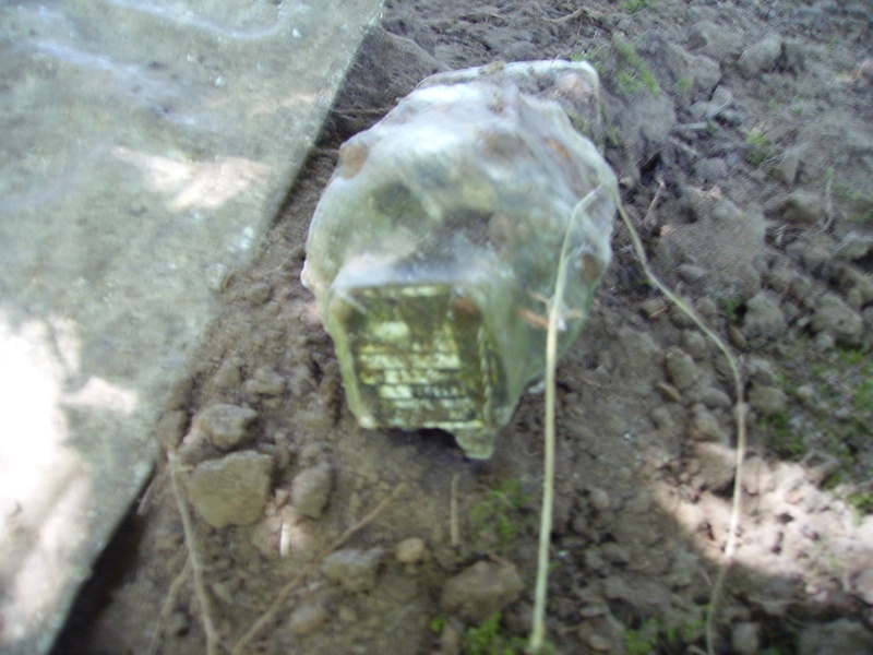
Page Updated 11th March 2012 Oxygen Cylinder – We Think it Could be a ‘Bale Out Bottle’? Any Ideas? Numbers on it Look Like: E432 LARE 214 1/2 Found at Burtonwood on the 11th of March 2012.
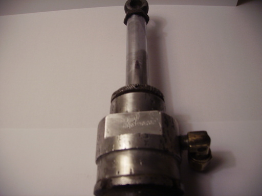
Hydraulic CylinderP-51D undercarriage fairing door (wheel cover) actuating strut. 106-58041: Strut Assembly 106-58702: Operating Strut End Serial No. 10656-2304 Assem 106 58041 E38 106-58702 Found at Burtonwood on the 4th of March 2012.
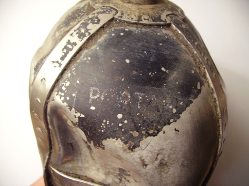
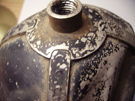
We Aren’t Sure What This is Really? We Thought it Was a Portable Oxygen Bottle Because it Has The Words’POATAB’Written on The Top of The Cylinder (Photo 2 Below). It Also Has These Numbers Imprinted Around The Neck of The Cylinder: ‘800 3-43’ Any Ideas What This Item is or ANY of The Other items Are on our Site? Contact: [email protected] Found at Burtonwood 12th February 2012.
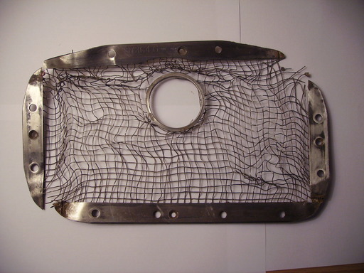
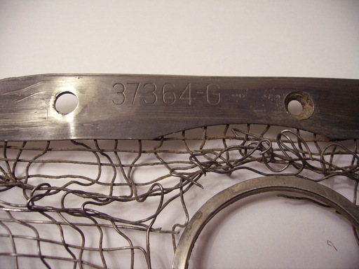
This is an Allison Engine Carburettor Grill From a P38-Lockhead Lightning. It Also Has These Numbers Imprinted on it: ‘37364-G’ Found at Burtonwood 12th February 2012.
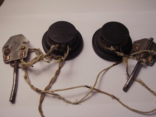
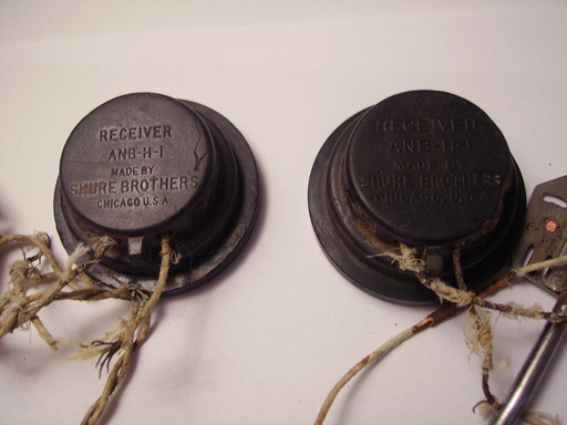
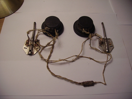
Aircrew Headphone Receivers. Found at Burtonwood 29th January 2012.
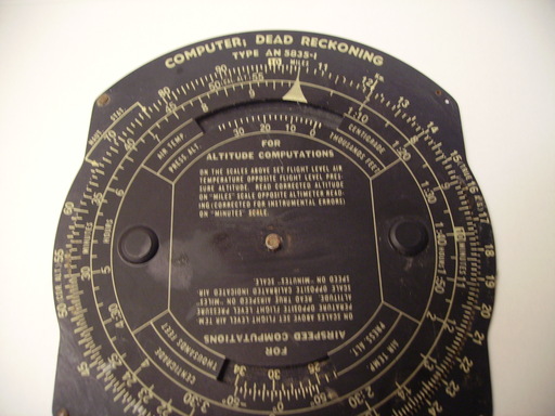
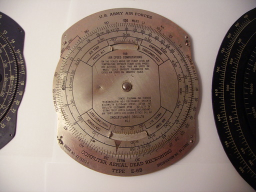
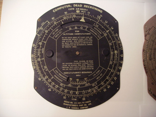
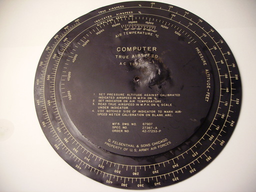
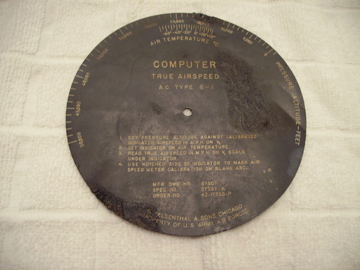
Computer True Airspeed A.C. Type – G-1 Found at Burtonwood 29th January 2012.
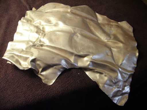
We Aren’t Sure About This Part? It is Obviously an Aluminium Alloy Aircraft Part. The Part Number is: F912-499-63 If You Know What This Part is From Then E-Mail Us …. Found at Burtonwood 23rd January 2012.
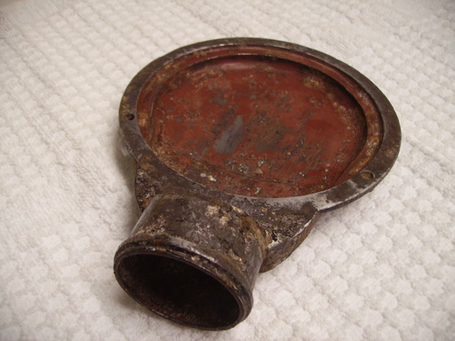
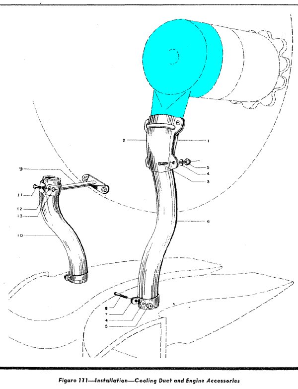
Air Cooling/Ducting Component off a P47 Thunderbolt. The Part Number is: EA-105871 Found at Burtonwood 23rd January 2012.
The ductwork (shown below) blows cooled air onto the engine’s electrical generator. However, the generator itself was a standard US supply item, Generator, AC, No. 95-32274, designed & built by……Fairchild.
Anyone Know What This Part is From? It is a Plexiglass Canopy Part With Olive Green Frame. There is an Identification Symbol On This Part. It Has a Circle WithHTin the Top Half & Some More Letters Beneath it, But We Cannot Make Them Out? Found at Burtonwood 23rd January 2012.
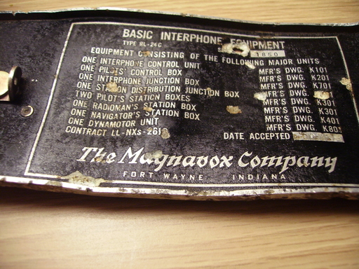
Basic Interphone Equipment From The Magnavox Company Fort Wayne Indiana. Type RL-24C. Found at Burtonwood 15th January 2012.
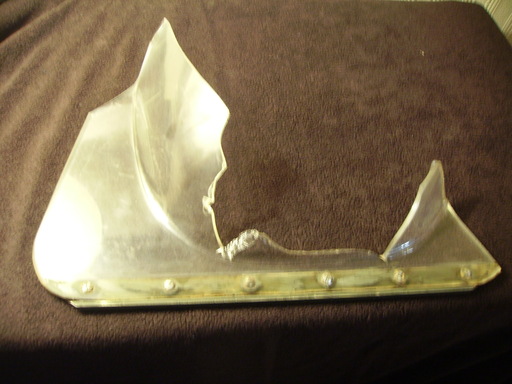
Aircraft Aluminium P47 Supercharger Wastegate Shroud, With Part Number Visible As Shown in Photos. Found at Burtonwood 15th January 2012.
The bulge at the top is to clear the flap operating mechanism, so the post and starboard shrouds are mirror images. Here’s a port-side one like ours & even the four bolt holes match up:
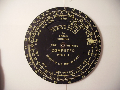
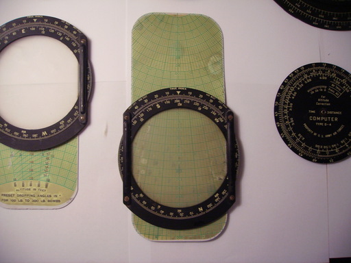
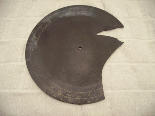
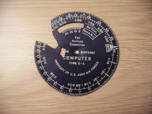
Navigator’s Computer Time & Distance Dial (We Think?). Found at Burtonwood around 15th January 2012.
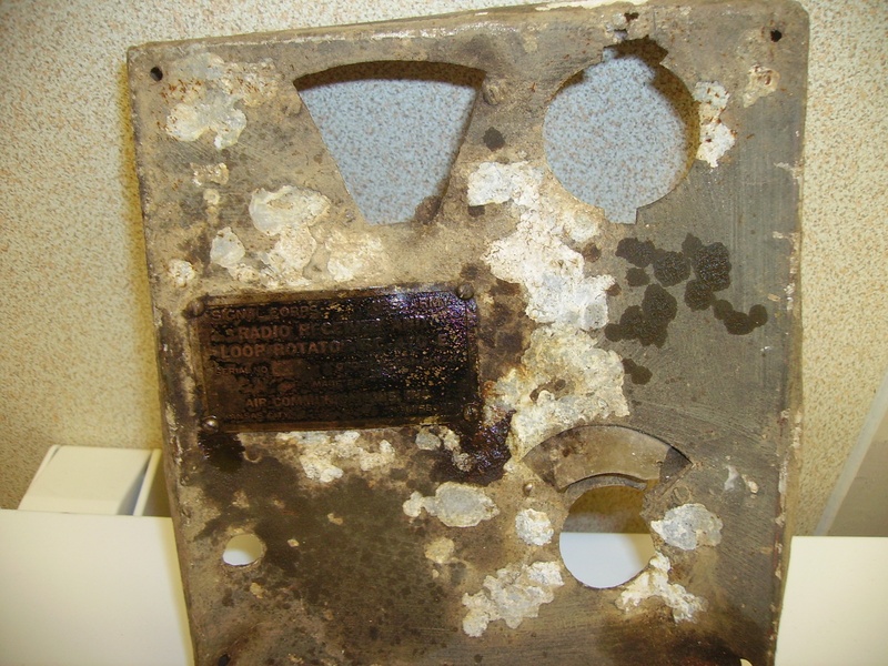
USAAF Aircraft Cockpit Part. Found at Burtonwood around July 2011.
The plexiglass frame is painted olive drab green on the outside & black on the inside, with 2 red-painted levers with catches on, which move up and down a yellow sign with red writing, which reads ‘Emergency Use Only’. I have looked on Google images and found an image of the inside of a Liberator B24 & I think it looks exactly the same. Curved Plexiglass. Found at Burtonwood August 2011.
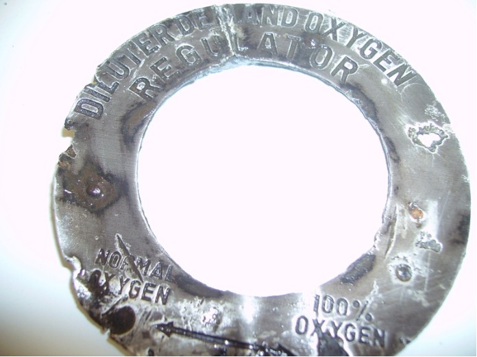
Diluter Demand Oxygen Regulator Plate. Found at Burtonwood August 2011.
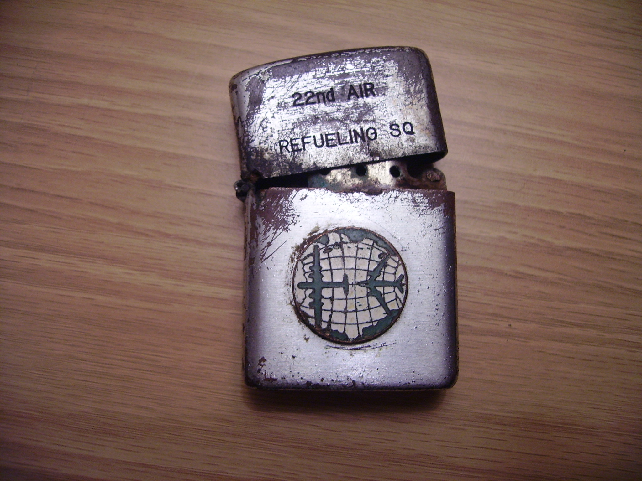
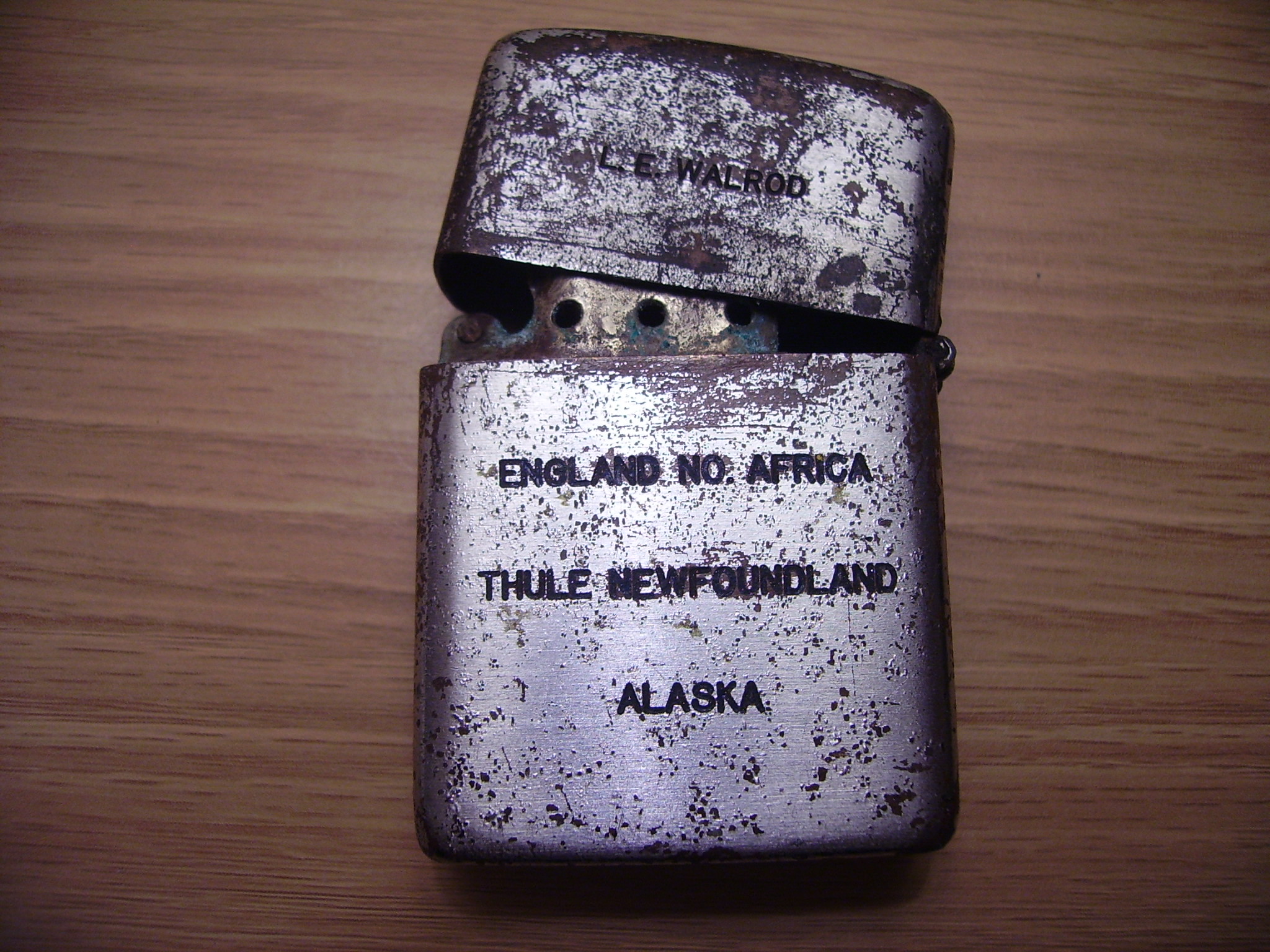
Zippo Lighter Found at Burtonwood at Gate 4 Near to The Original Entrance (Photo Below). Photo Took in 1984.
This lighter belonged to L.E. Walrod. of The 22nd Air Refuelling Squadron. On the reverse side of the lighter it has inscribed: ‘England No. Africa Thule Newfoundland Alaska’
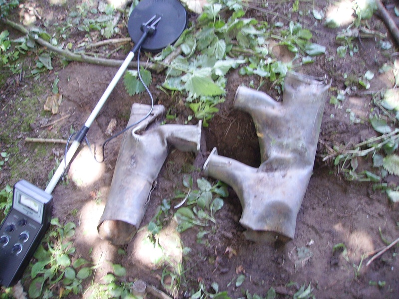
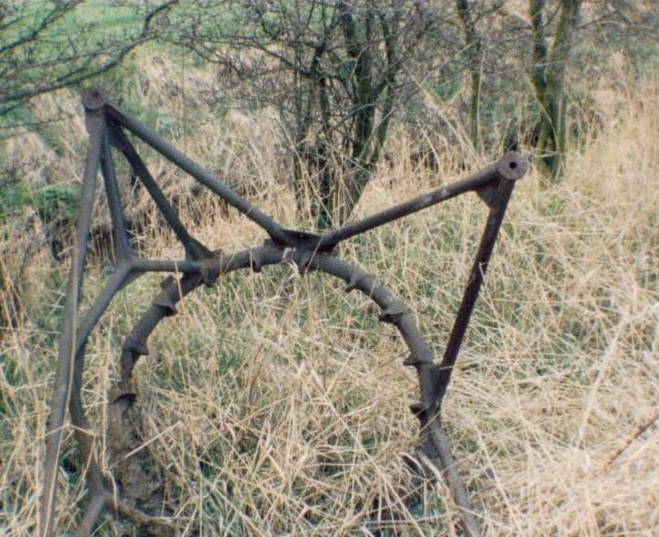
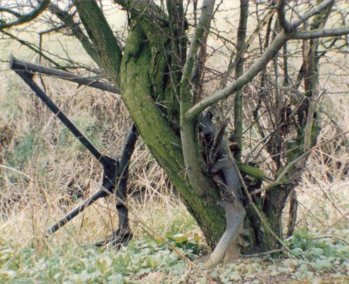
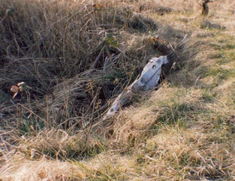
The Following Photos Are From a Classified Location Near Burtonwood That Were Taken in 1995. Aircraft Engine Mount.
© Historic Aviation Military — All rights reserved Non Commercial — Non Profit Website / Organisation