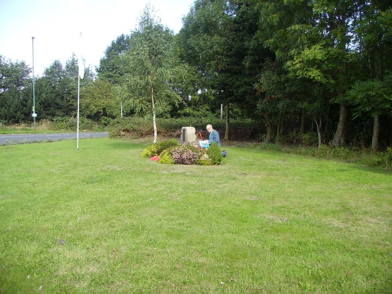
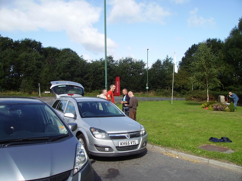
Lawrence Critchley (red shirt), Mike Dawson (blue jacket), Richard Houghton (brown jumper) are dedicated to keeping the history of the airfield of HMS Ringtail ‘alive’. The ‘guys’ can be seen here talking to Brian Lea who was stationed at HMS Ringtail/camp 2 for a short stay during his national service around 1955.
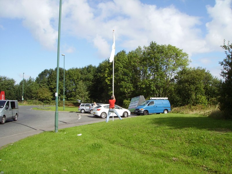
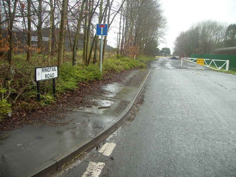
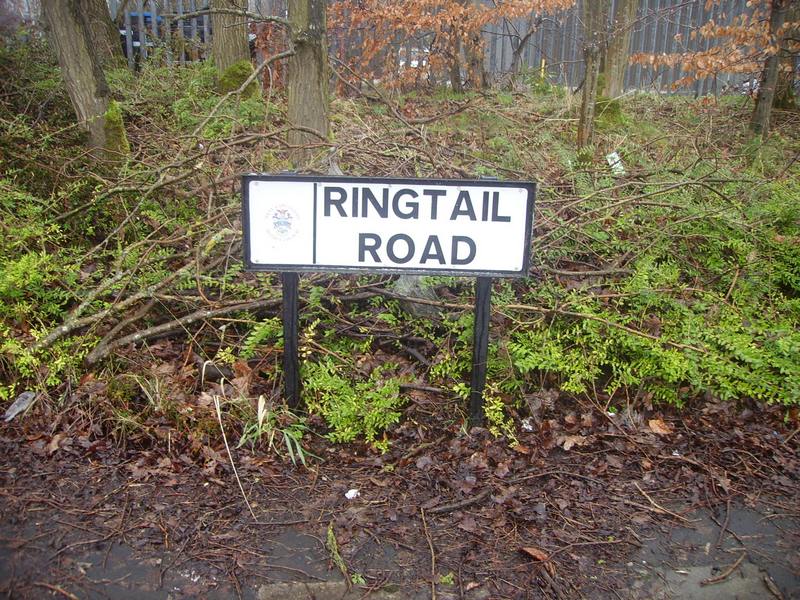
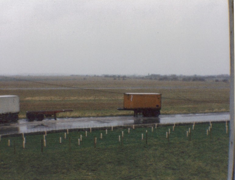
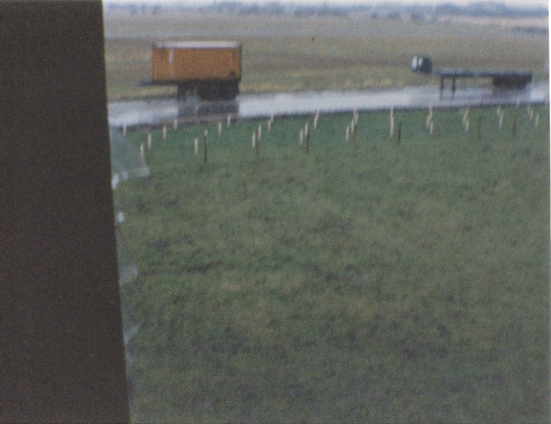
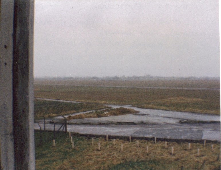
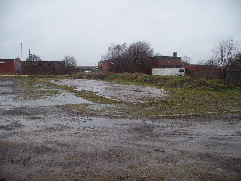
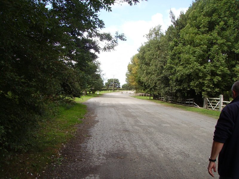
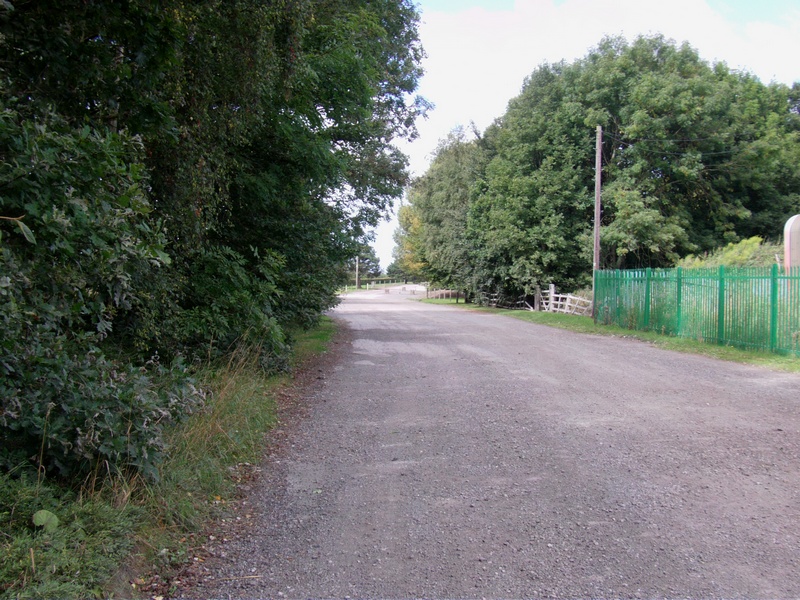
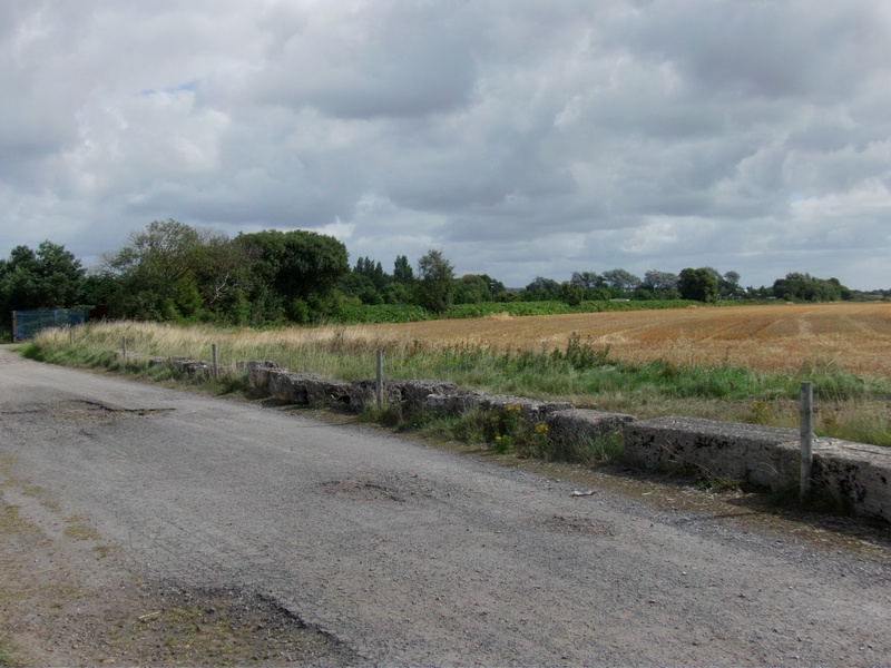
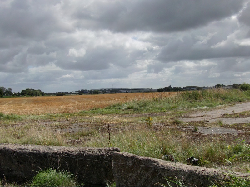
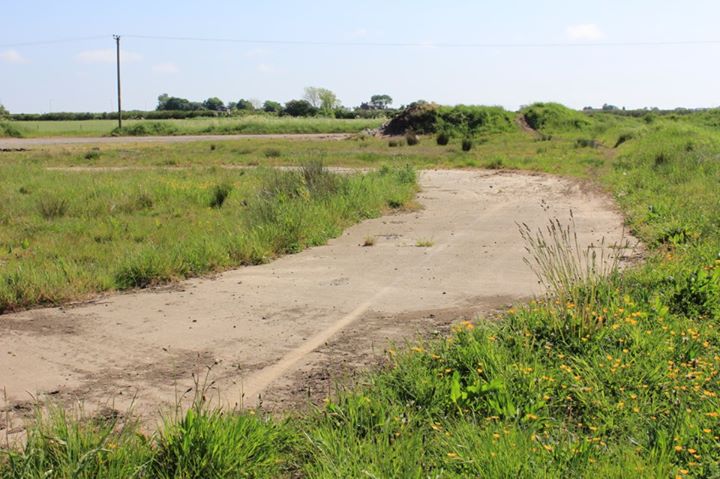
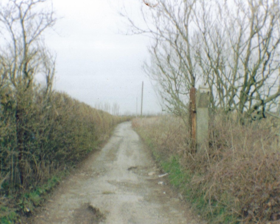
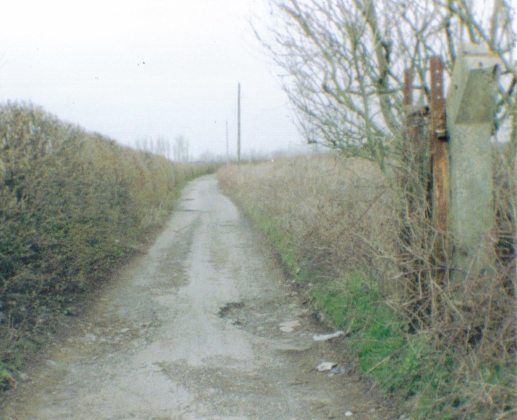
Ringtail Road Keeping the History of the Airfield ‘Alive’ the Road has been Named ‘Ringtail Road’. In the Distance (past the white barrier) is the ‘Old’ Remains of the North Perimeter Track Facing West
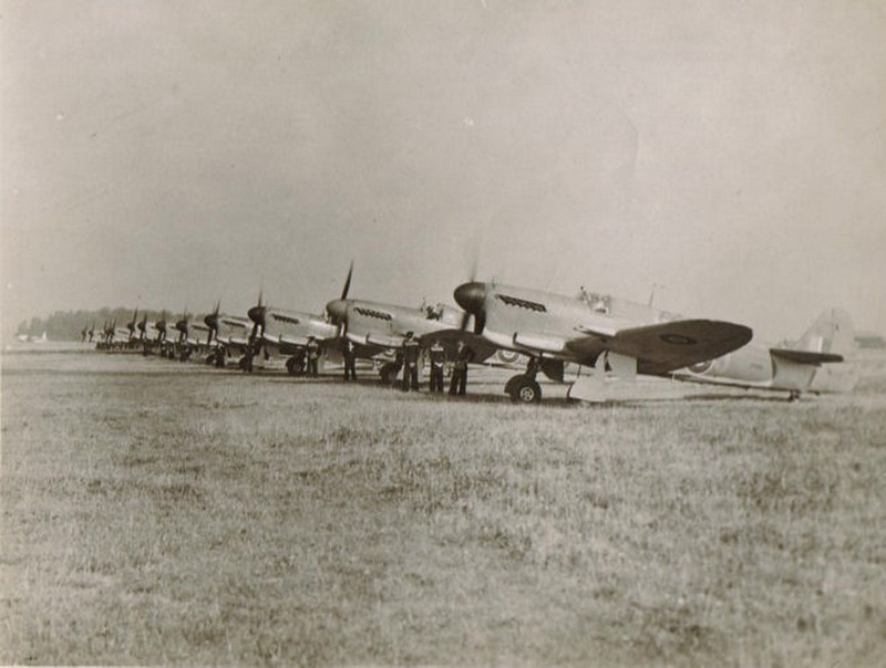
1771 Squadron at HMS Ringtail, the Squadron arrived on the 3rd March 1944 and departed at the end of July 1944.
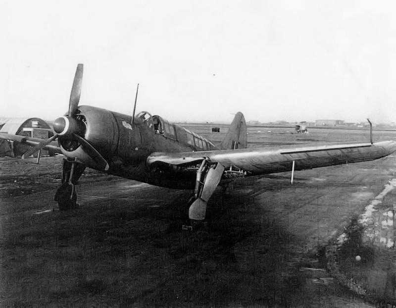
1820 Squadron at HMS Ringtail. The Squadron arrived on the 11th of August 1944 and was disbanded in December 1944.
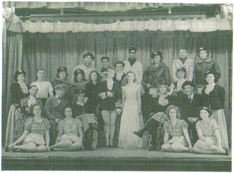
Christmas of 1944. Panto of Cinderella.
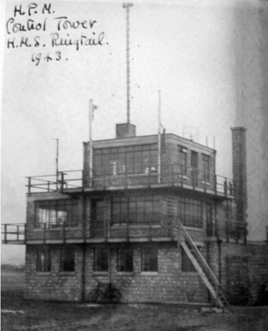
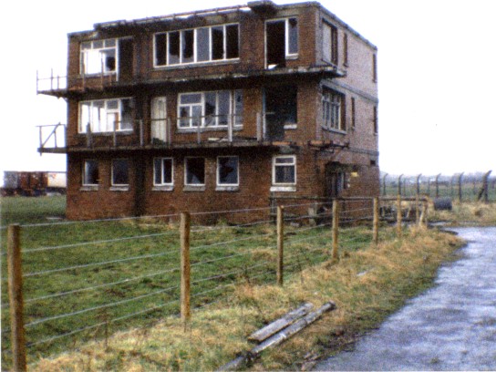
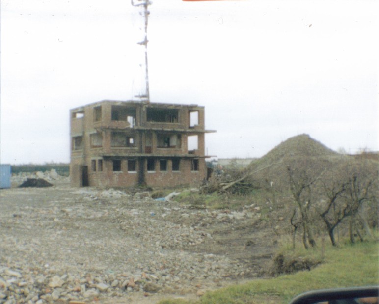
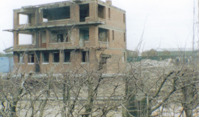
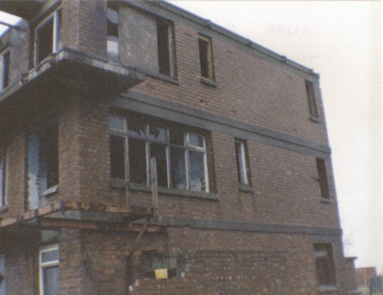
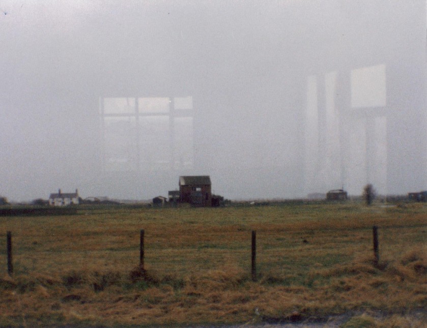
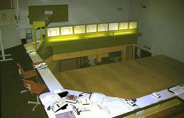
Control Tower Photo Just Before Demolition ….
Control Tower Photo Just Before Demolition ….
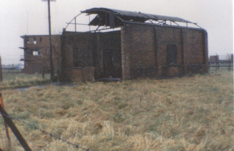
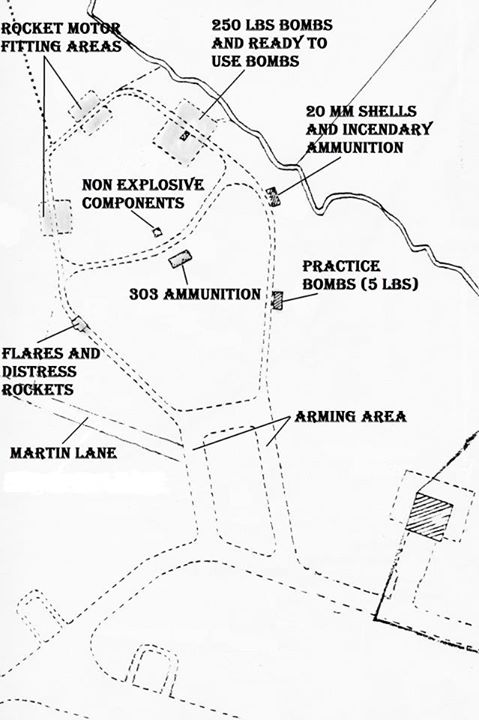
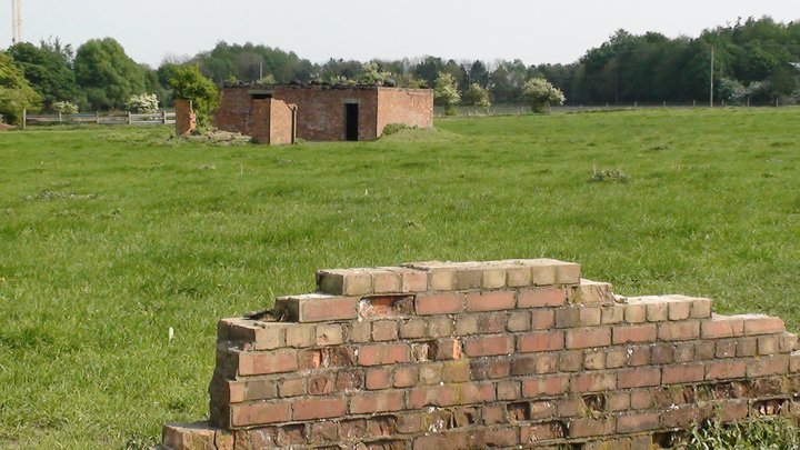
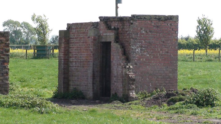
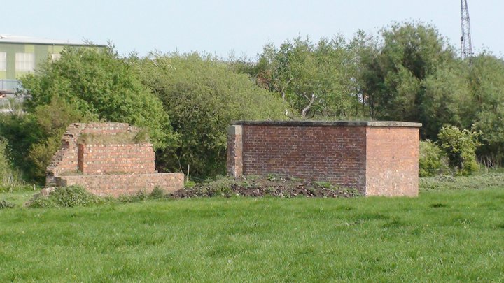
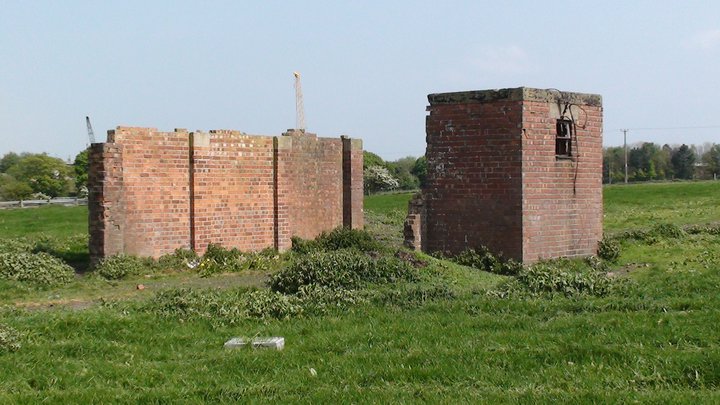
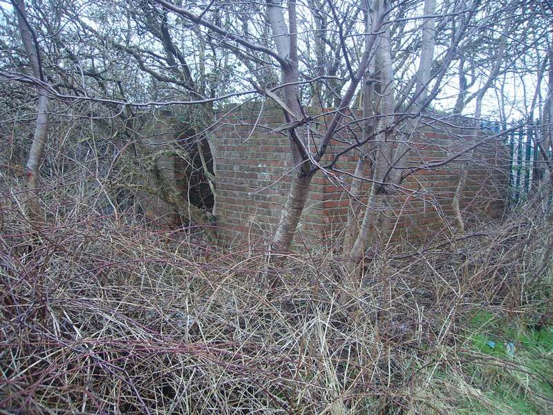
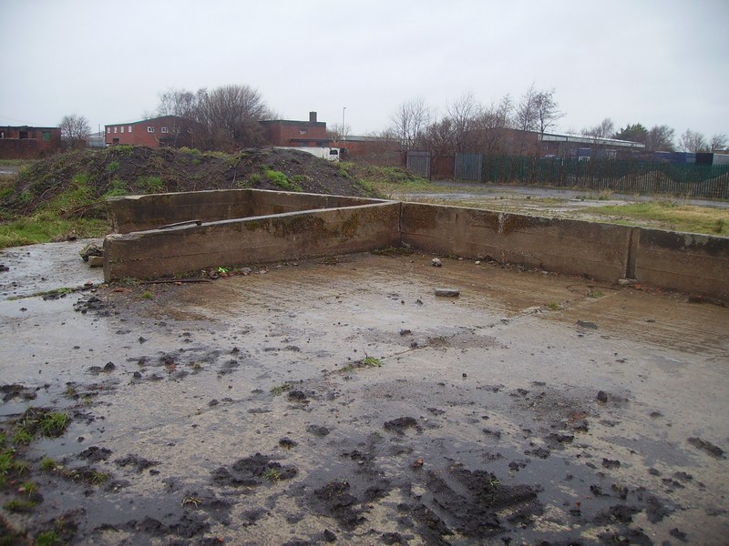
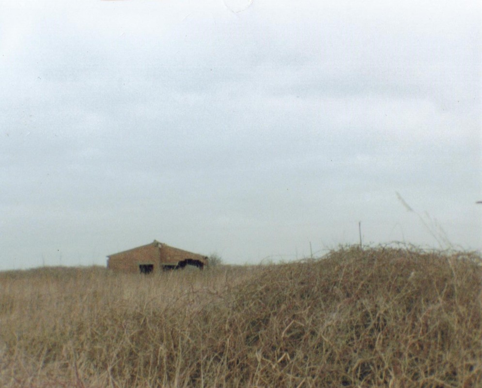
In the foreground are the remains of the rocket motor fitting area blast walls, and in the distance can be seen the remains of the non explosive components building (small) and 303 ammunition building (large), on the explosives area, 29th April 2011.
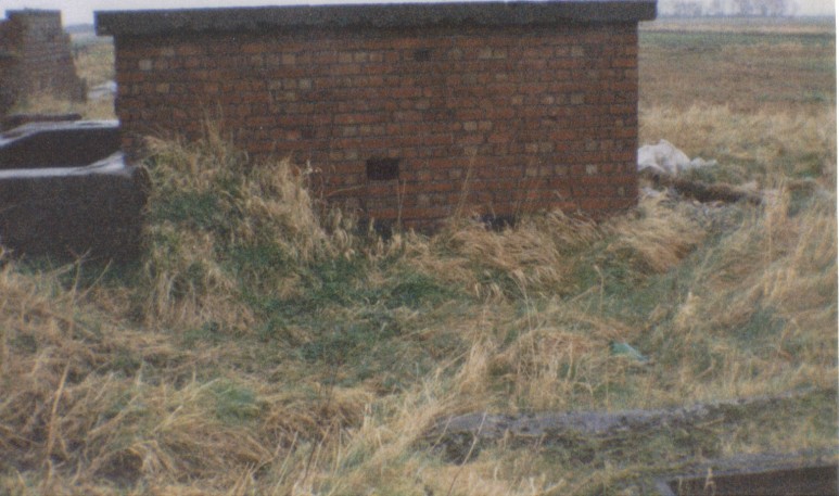
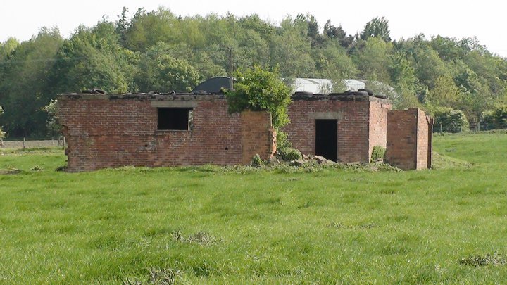
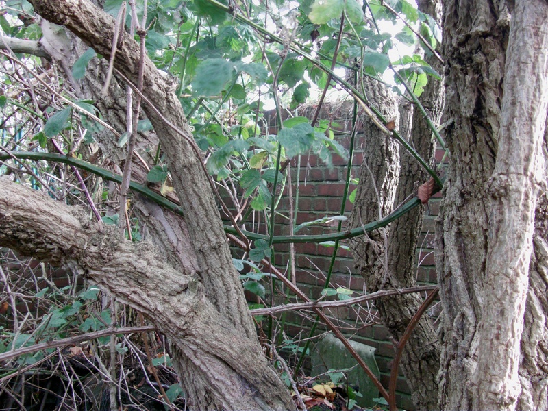
Remains of the 20mm shells and incendiary ammunition building on the explosives area, 29th April 2011.
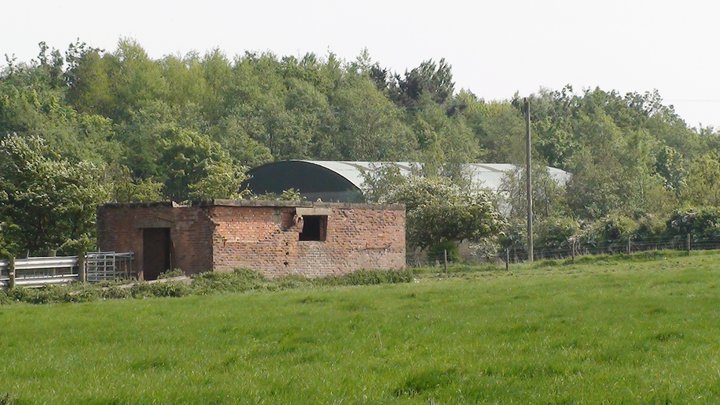
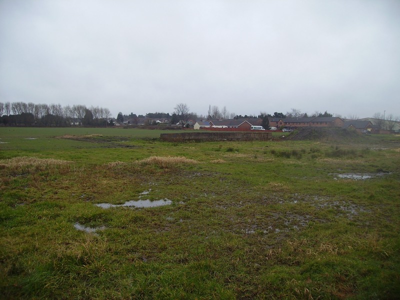
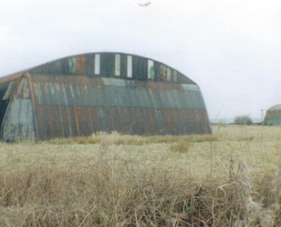
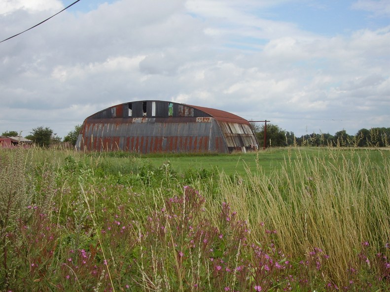
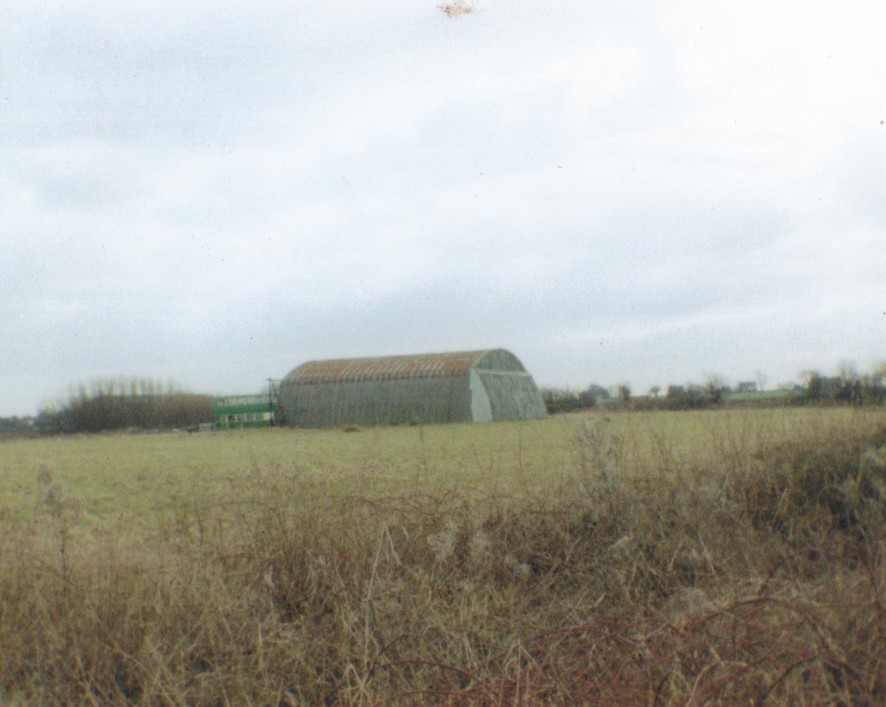
Remains of the 5lbs practice bombs building on the explosives area, with one of the original mainhill hangers in the distance, 29th April 2011.
Remains of the 20mm shells and incendiary ammunition building on the explosives area, 29th April 2011.
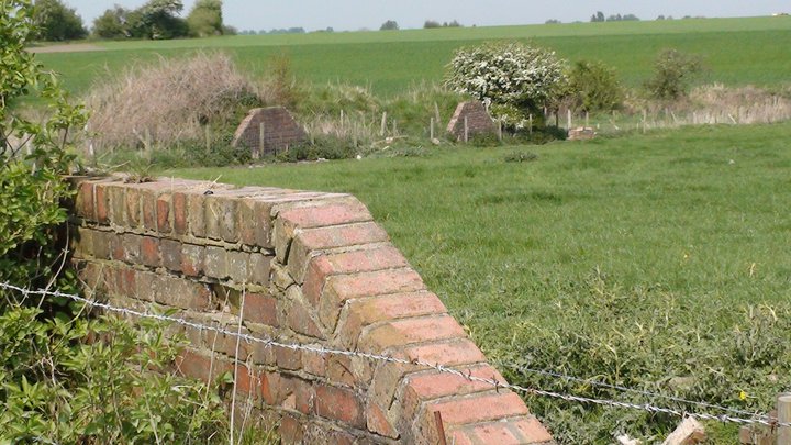
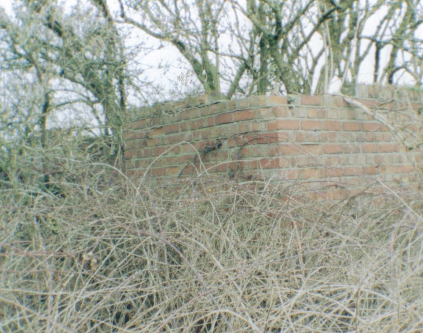
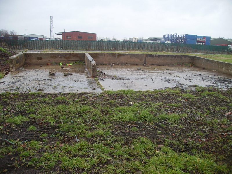
Remains of the blast wall (left) and the ready to use bombs / 250lbs bombs building on the explosives area, 29th April 2011.
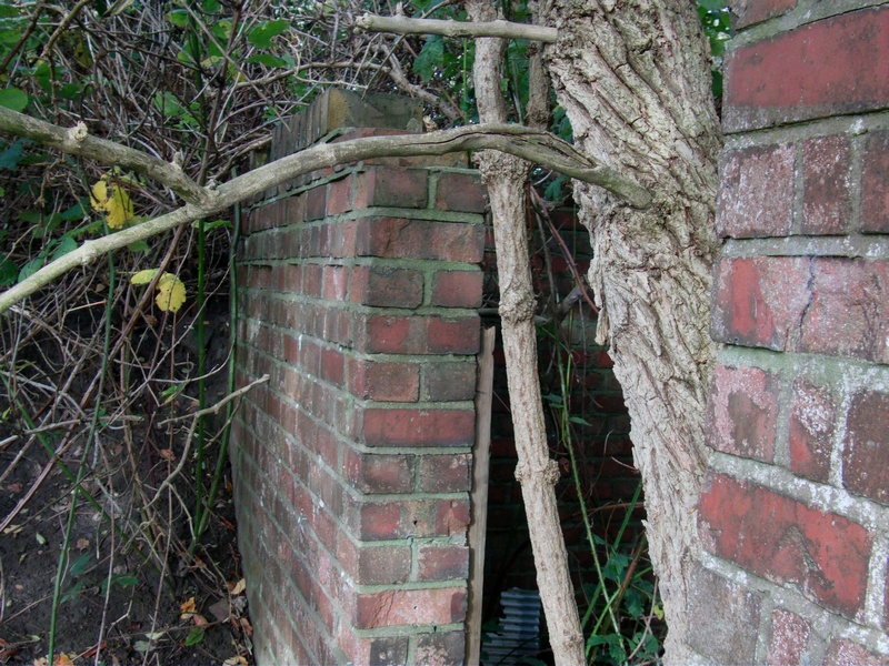
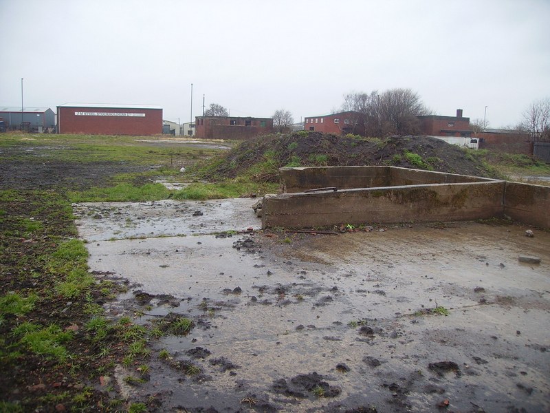
Remains of the blast walls on the rocket motor fitting area, on the explosives area, 29th April 2011.
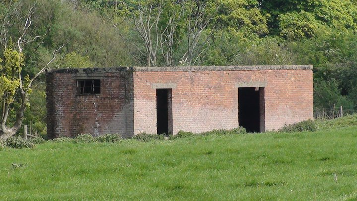
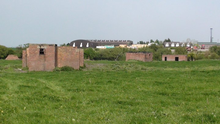
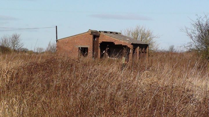
Remains of the flares and distress rockets building (left), 303 ammunition building (centre) and the 20mm shells and incendiary ammunition building (right), on the explosives area, 29th April 2011.
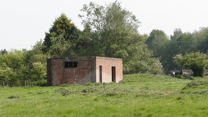
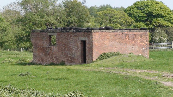
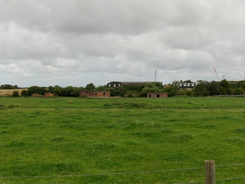
Remains of the non explosives components building (front) and the 303 ammunition building, on the explosives area, in the background can be seen one of the old mainhill hangars, 29th April 2011.
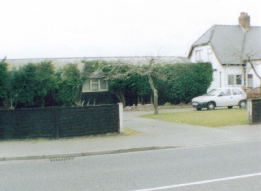
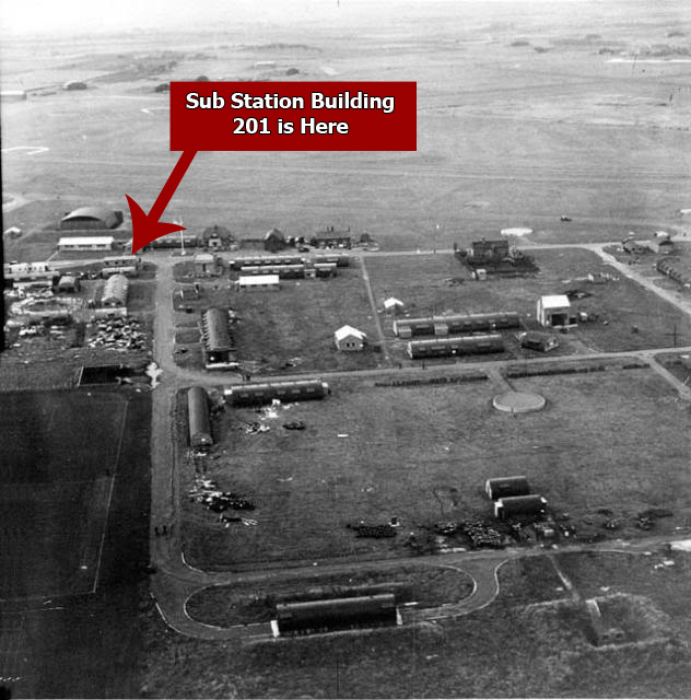
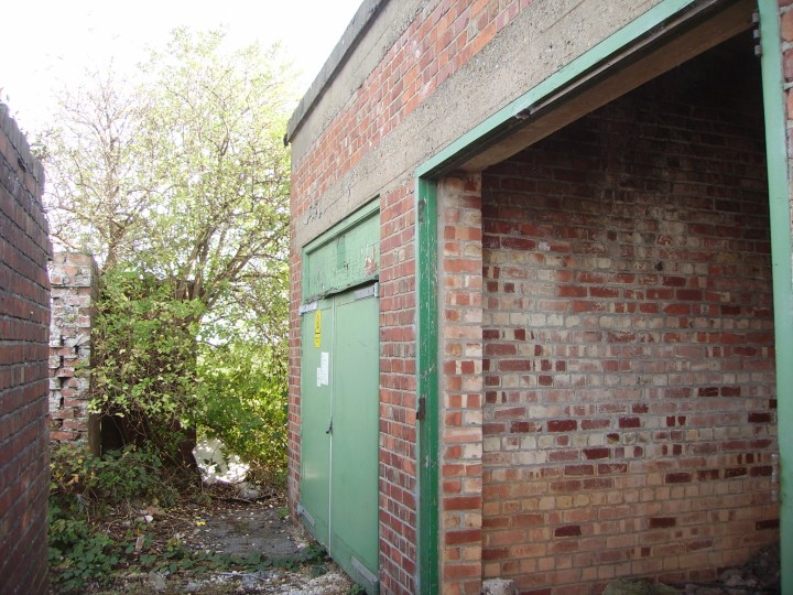
The Station Commander of HMS Ringtail’s House Called The Retreat (Date of Photo 2003) To the right of the photo is where the admiral of the camp lived and was called ‘the retreat’ and it was opposite the parachute packing house and the sub station. On the left of the photo is a nissen hut and was used as offices for the camp and later after WW2 it was used as a canteen for the civilian work force that worked on the airfield in the maintenance workshops. Built 1935 and demolished the 5th of February 2013
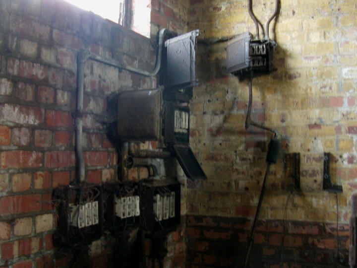
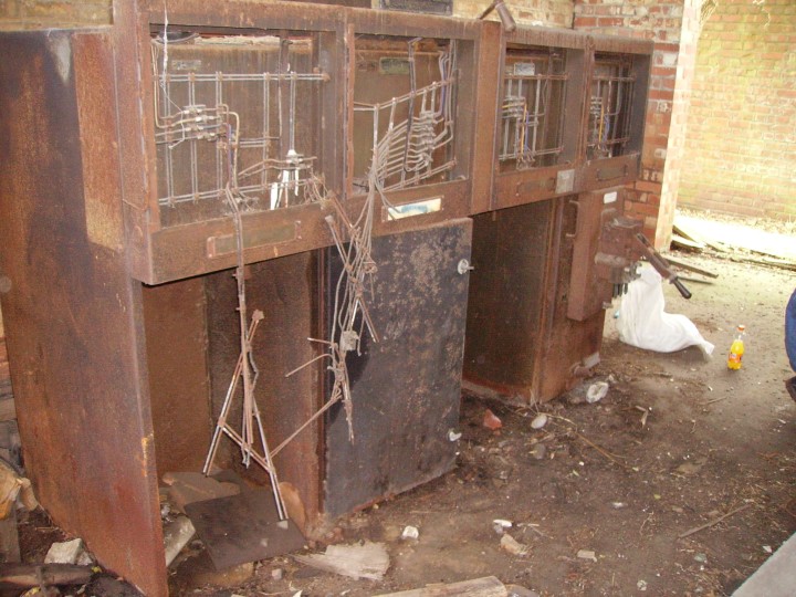
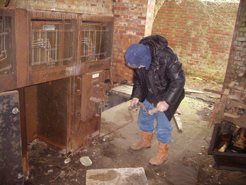
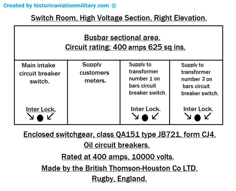
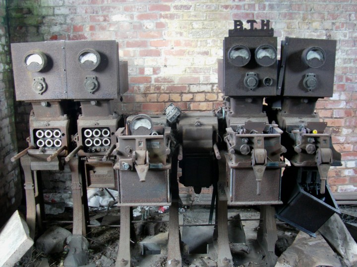
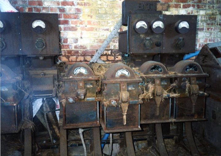
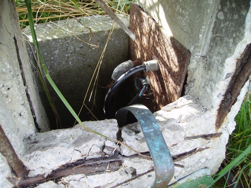
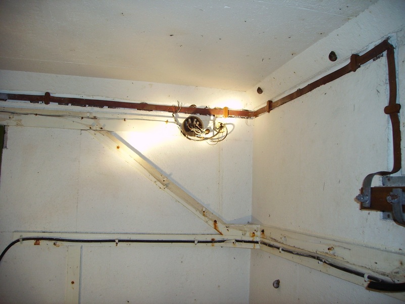
The dangling cables (as shown on the photo above) were attached to metering equipment (as shown on the photo below) Please note: The actual busbars are situated behind the top 4 enclosures. Malc Recently Found the 10,000 Volt Switchgear Interlock Handle Hidden under Rubbish (2015 Update Photo)
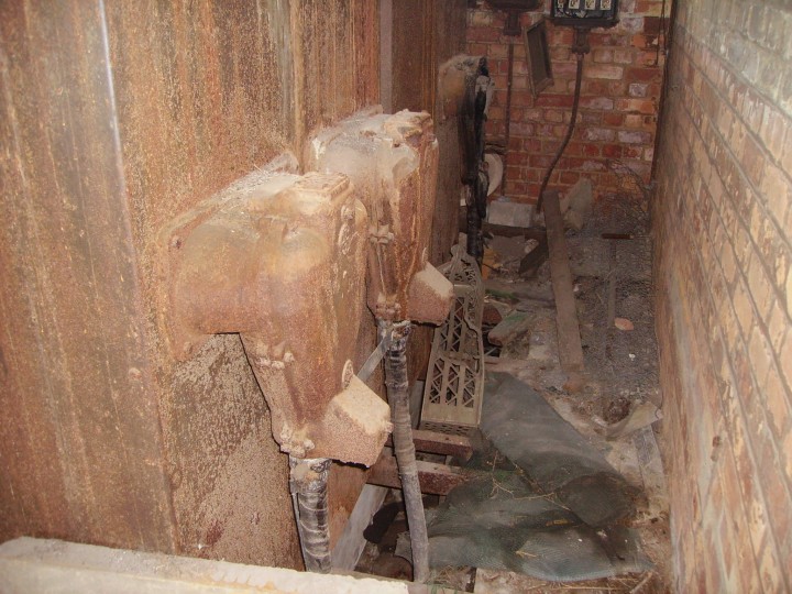
Image Below (Taken 2013) Shows The Rear of the High Voltage Switchgear, Showing the High Voltage Cabling Left to Right: Transformer No.2 Supply, Transformer No. 1 Supply and main intake supply cable
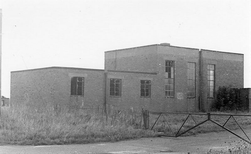
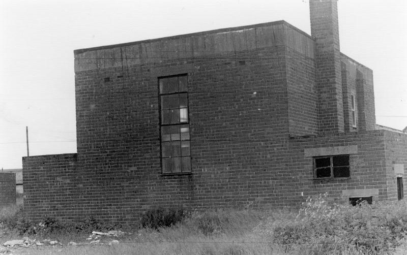
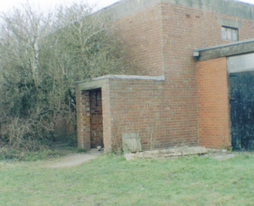
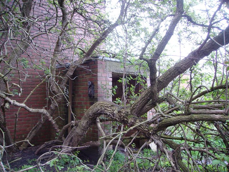
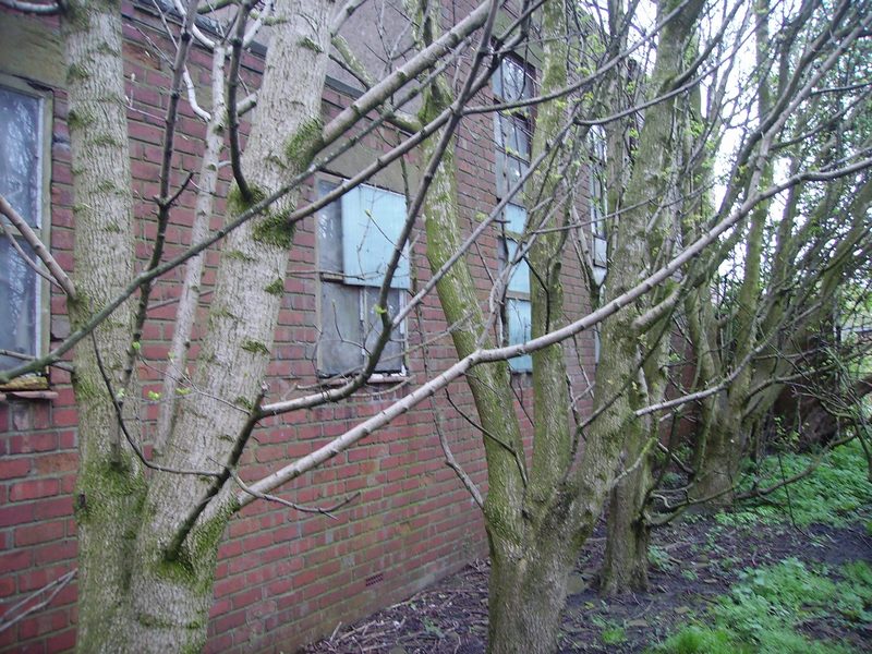
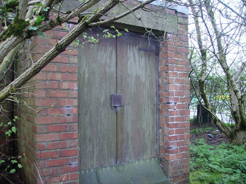
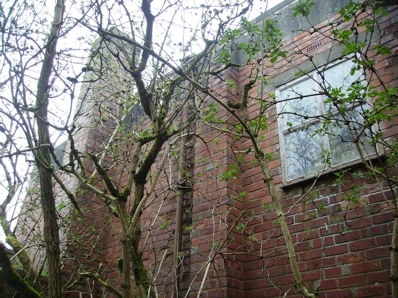
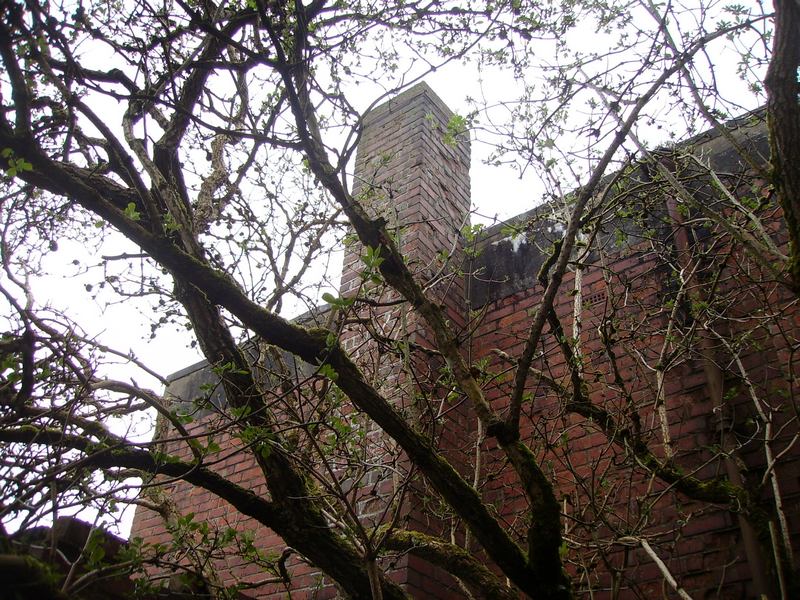
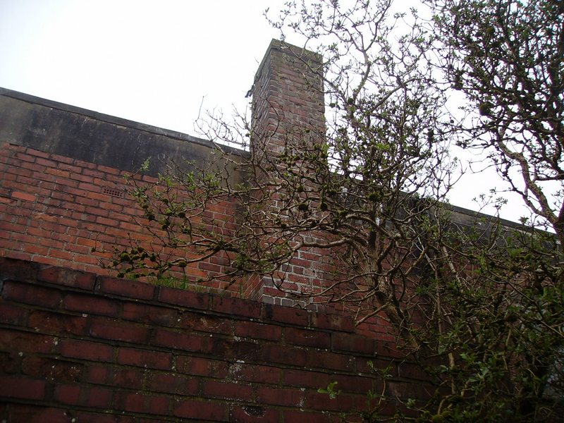
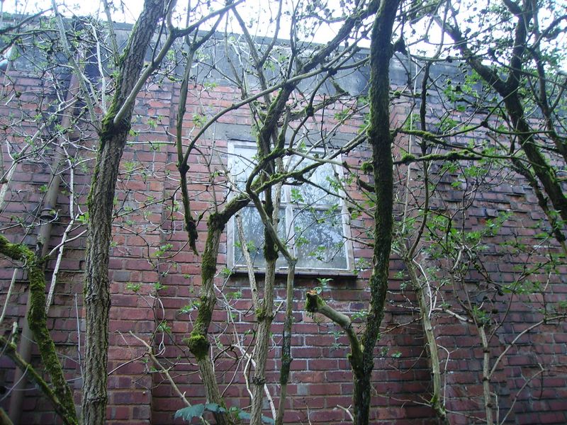
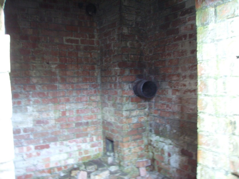
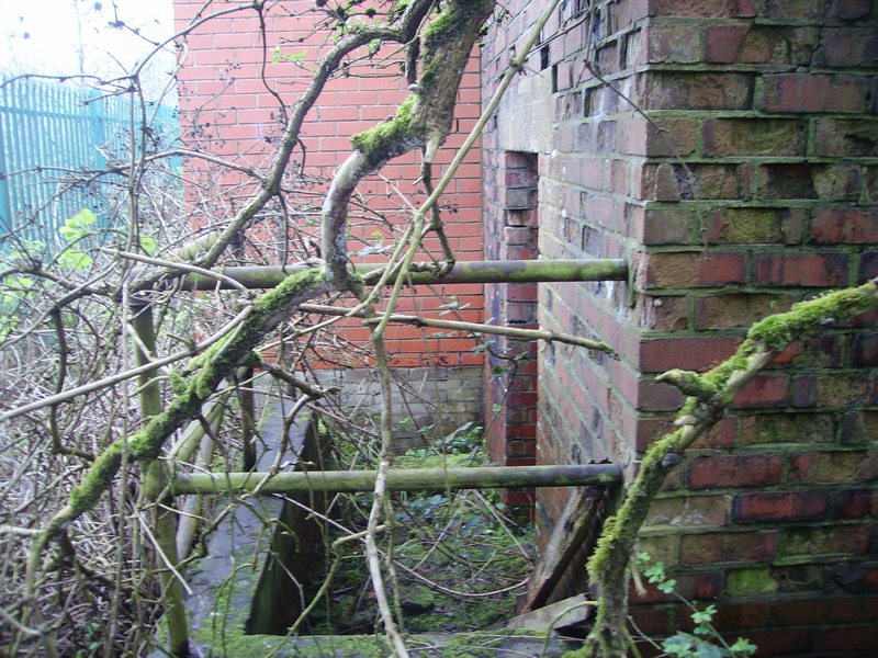
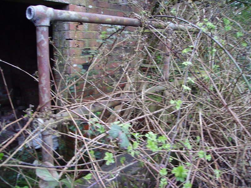
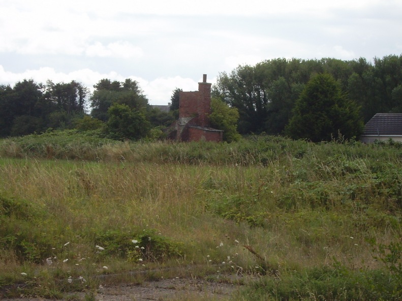
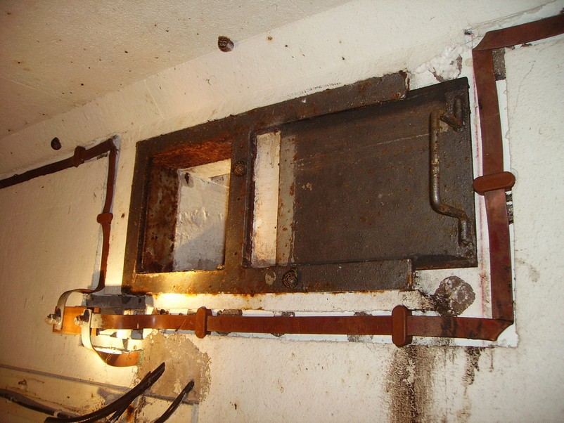
The right hand side of the parachute packing store shows the boiler house on the right of the photo below. The fuel and ash hatch can be seen just below the window to the right of the photo. The boiler chimney can also be seen.
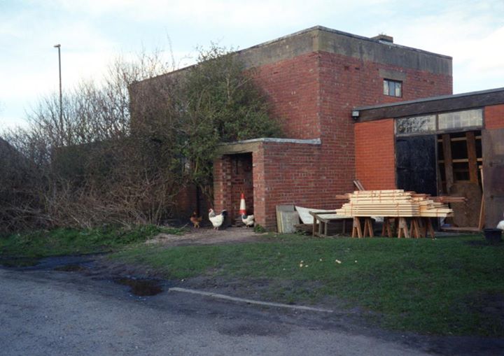
The photo above was taken in the 1970’s and as you can see below in the 2001 colour photo (taken at a slightly different angle) a modern building has been added to it. You can still see the large window but it has been reduced in height. The main entrance in the black and white photo is on the left and on the colour photo it is where the chickens are roaming.
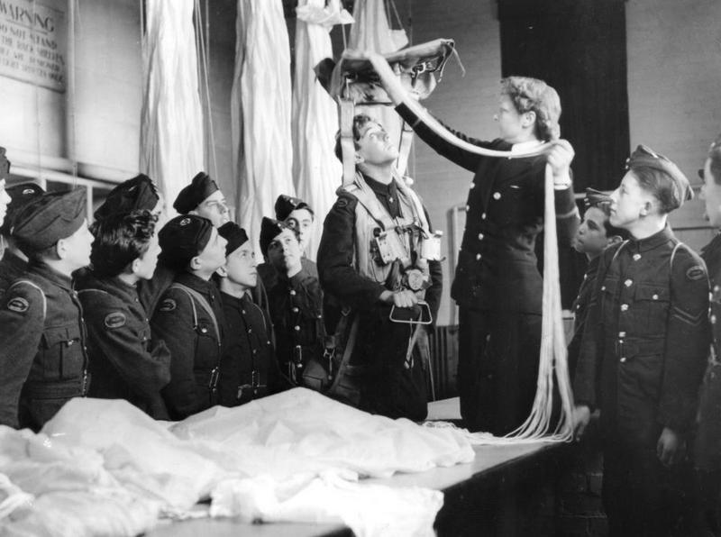
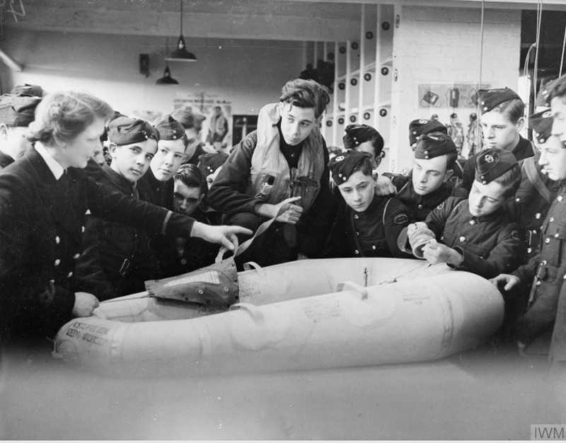
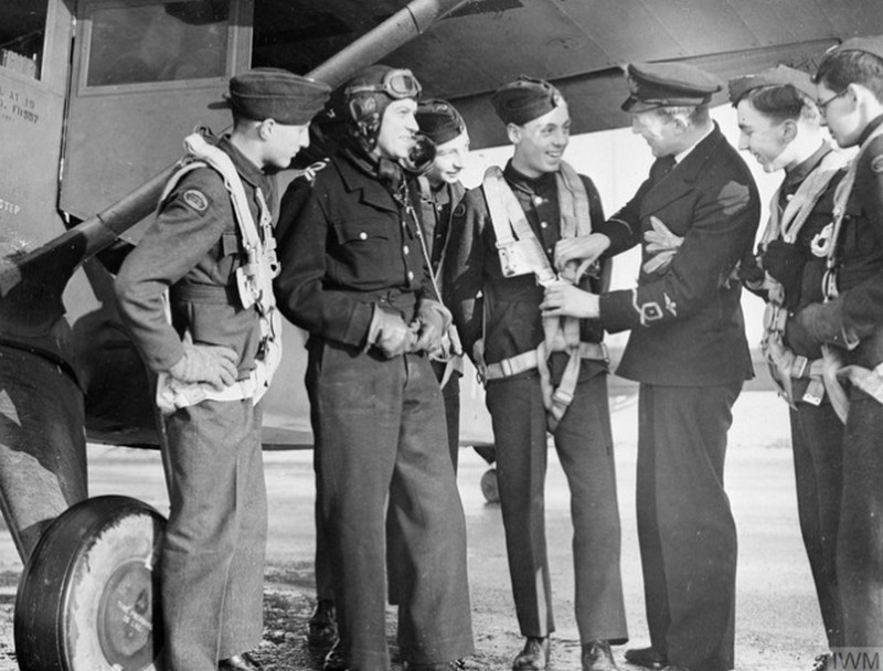
Air Cadet’s at Ringtail on the 9th of February 1945 in the parachute packing house … a WREN Officer shows trainee’s the working’s of a parachute. (Please note: IWM – Used under the IWM’s non commercial licence)
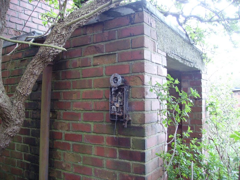
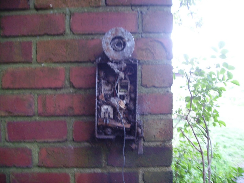
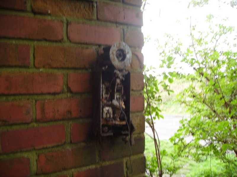
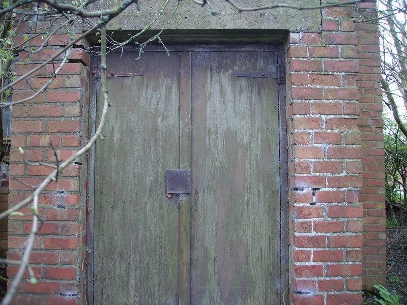
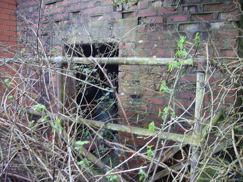
A fleet Air Arm officer explains the fitting of the parachute harness to ATC cadets while the pilot looks on. The front entrance shows an electrical cast iron switched fuse that looks like a light above it. It’s purpose unknown?
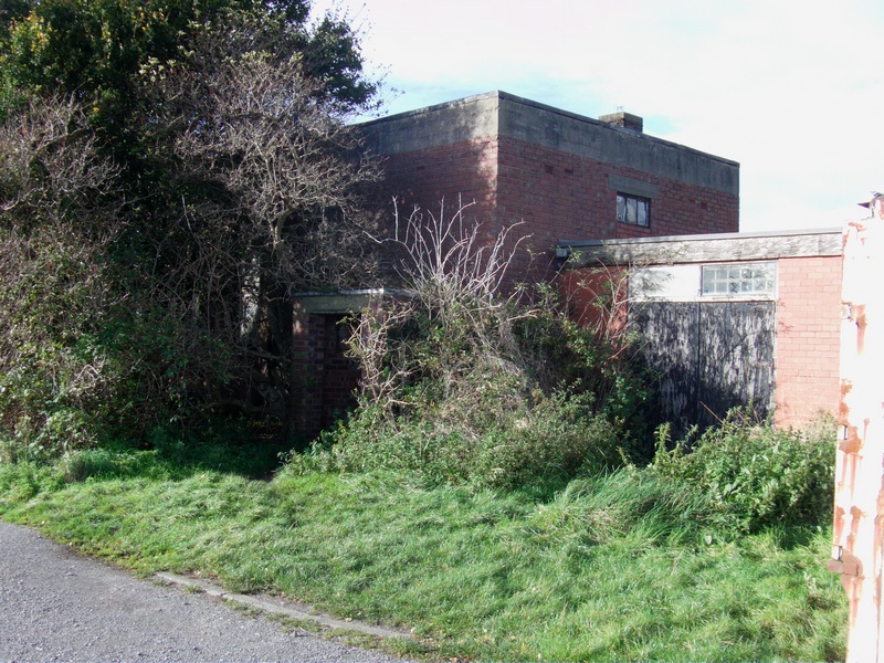
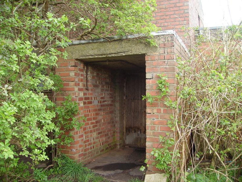
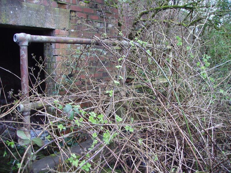
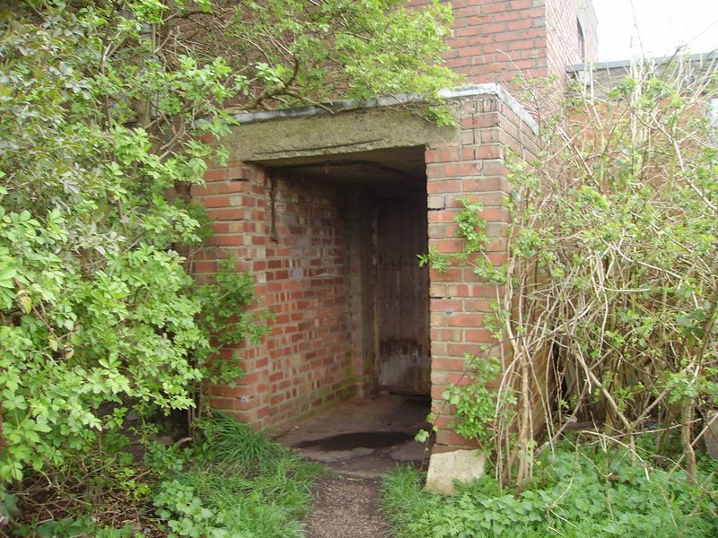
The front entrance view at a slightly different angle showing the back entry conduit that comes from the electrical switched fuse (above).
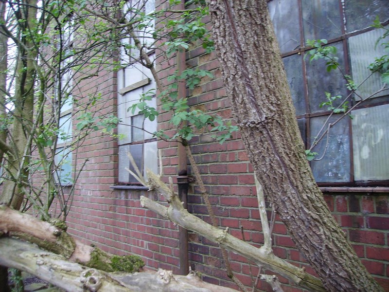
Front of the building with the packing room on the right and the parachute packing house store on the left.
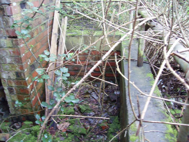
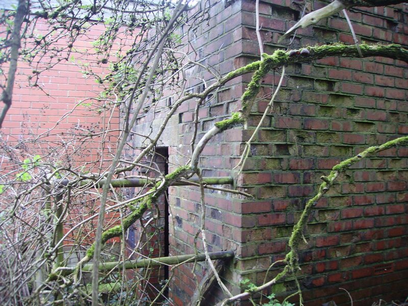
Steps down to the boiler room. The boiler room is semi sunken compared to the parachute building in general.
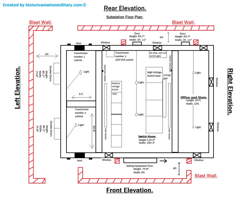
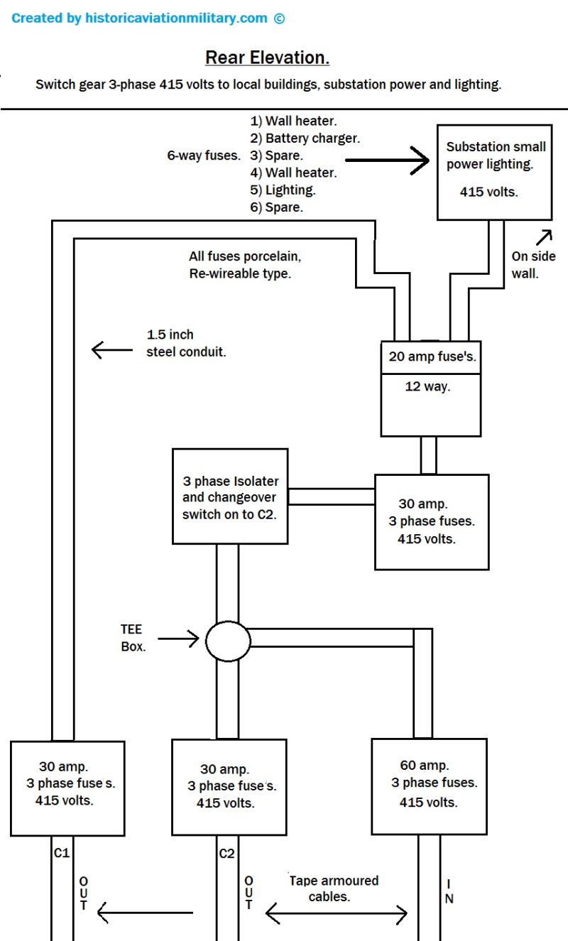
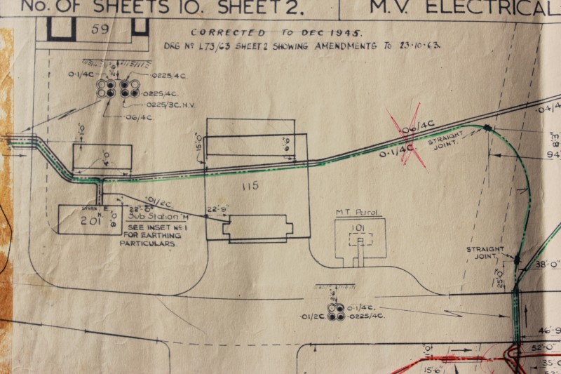
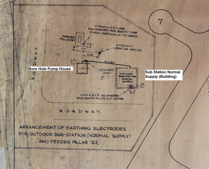
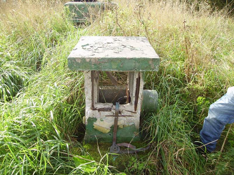
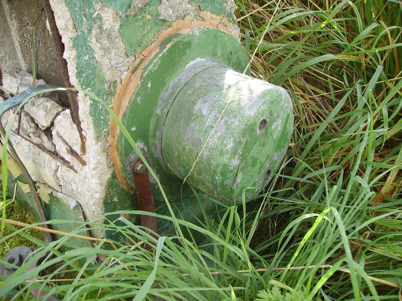
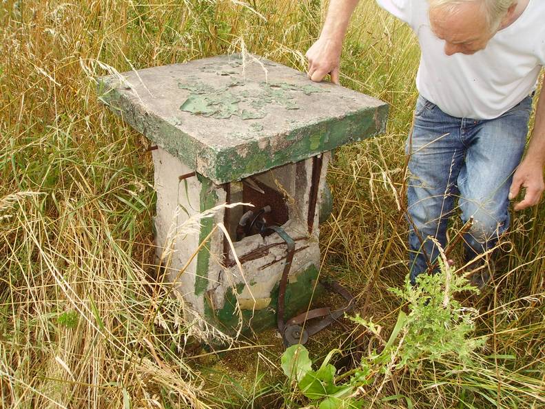
Electrical Drawing of The Sub Station Normal Supply Building 0.1/4C (3 Phase & Neutral) Supply Feeding The Bore Hole Pump House.
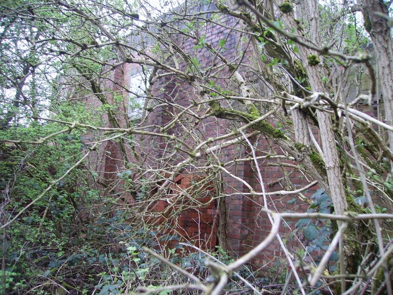
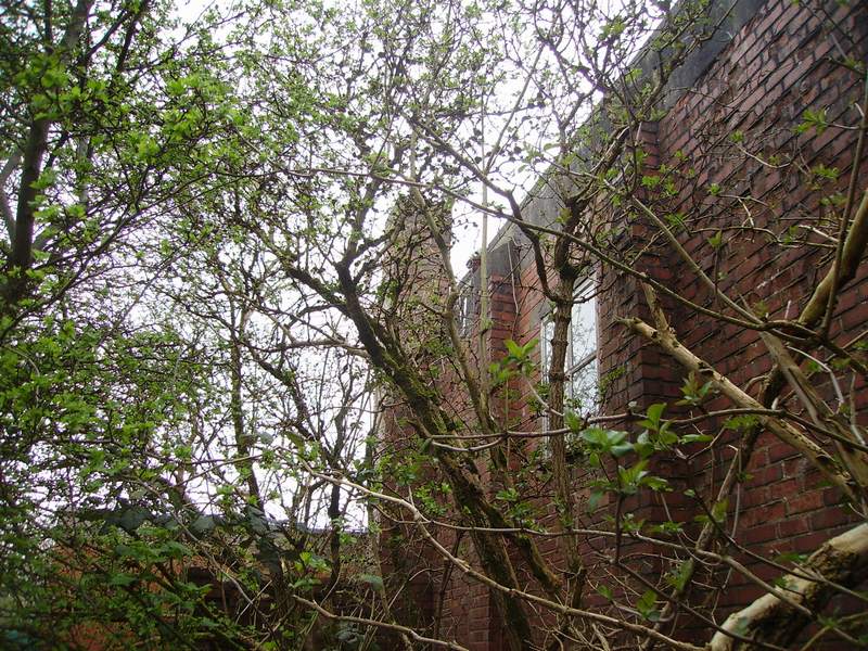
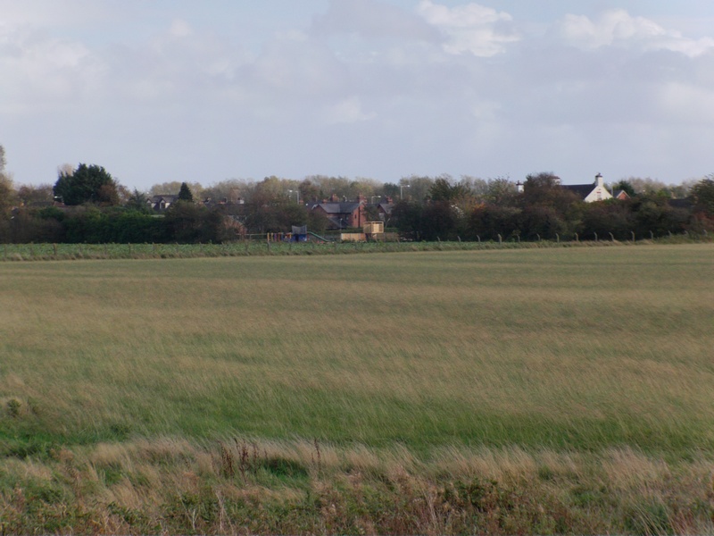
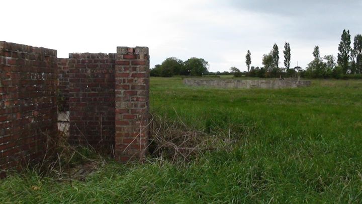
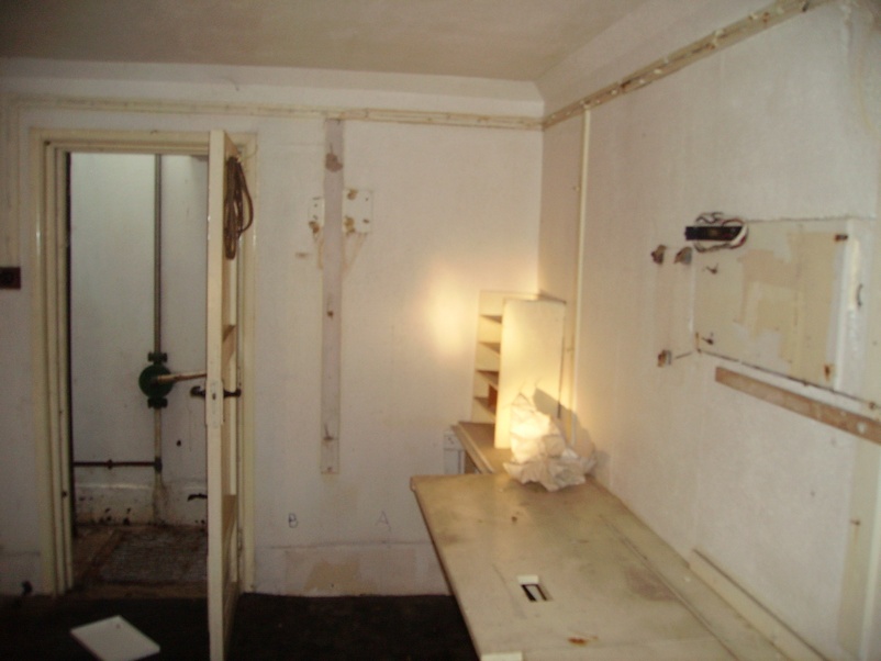
Civil Engineering Compound & Offices Area Foundations Camp 3 2015. What you can see is the civil engineering compound and offices area. The rear of the sub station is in the far left background and the parachute packing house and store is on the far right.
The Fuel & Coke Store. The fuel and coke store/area as you can see is split into 3 separate bays.
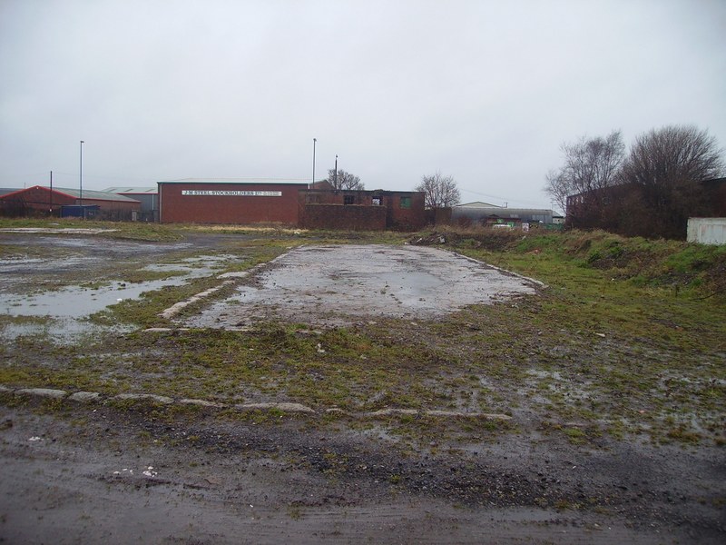
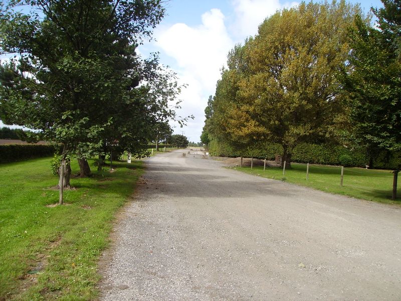
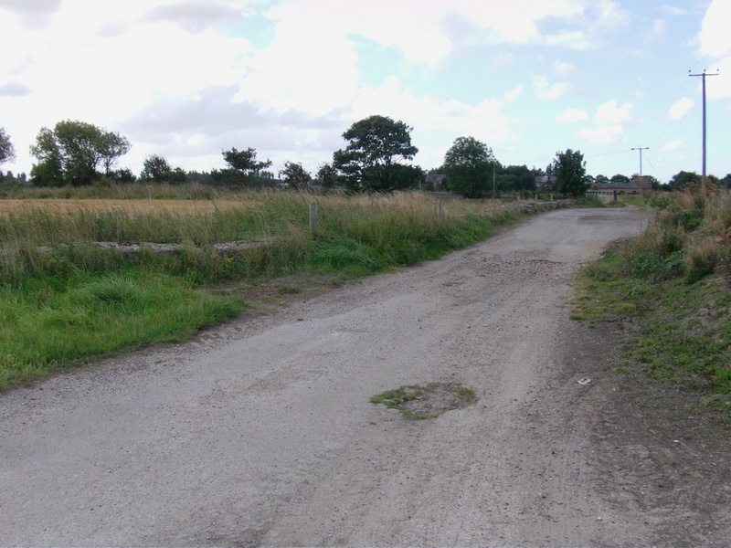
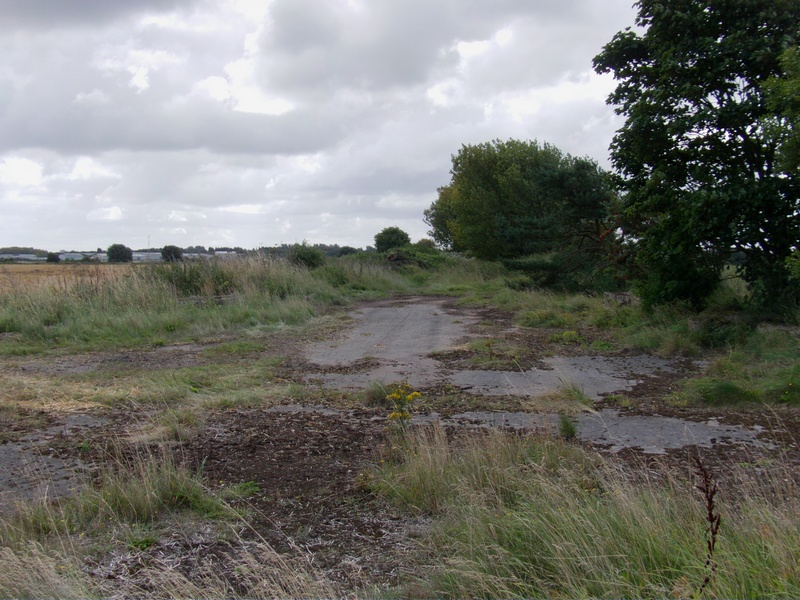
This Can be seen From the Remains of the North Perimeter Track Facing North. In fact it was taken from the perimeter track looking north.
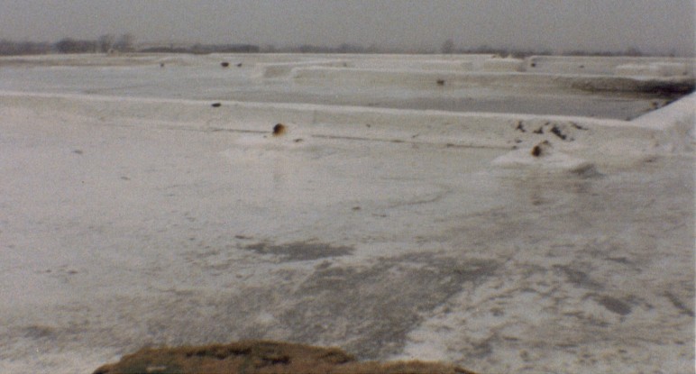
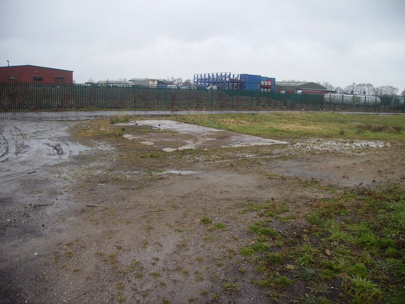
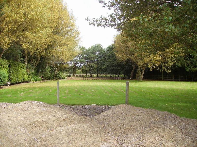
Continuation on From the Remains of the North Perimeter Track turning slightly left and in the distance where the tree line is, is the head of runway 17.
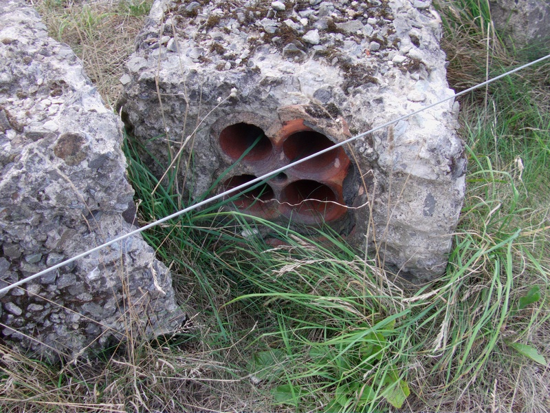
4 Way Stoneware Conduit Electrical Ducts Encased in Concrete on the head of Runway QDM170 (Runway 17)
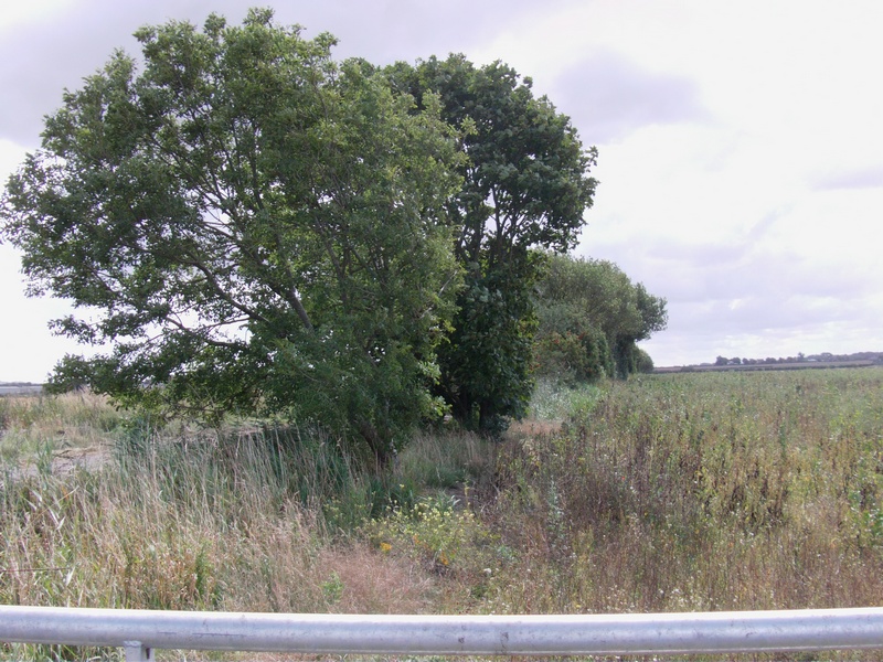
Head of Runway 17 Note: The communication mast just visible in the distance was next to where the control tower used to be .. (now demolished)
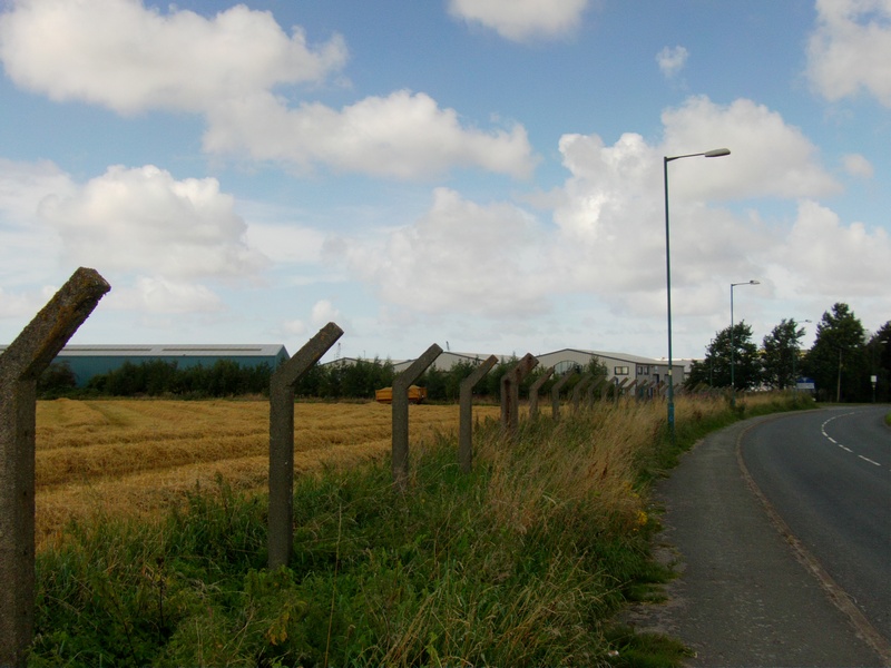
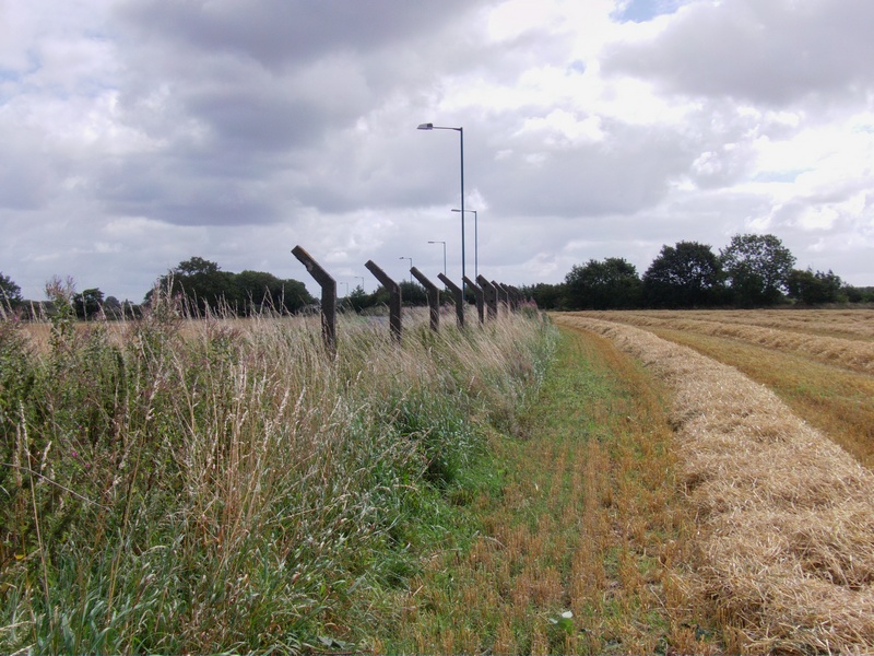
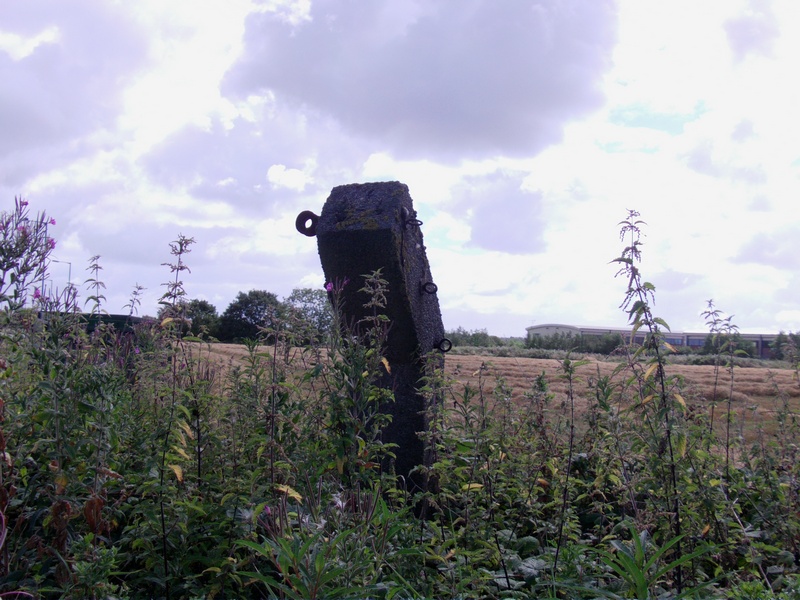
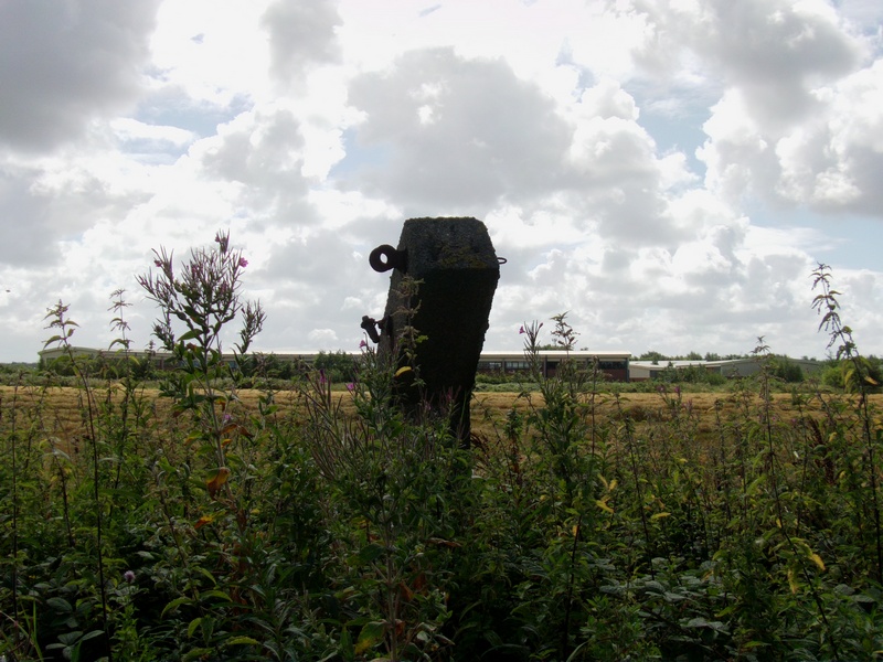
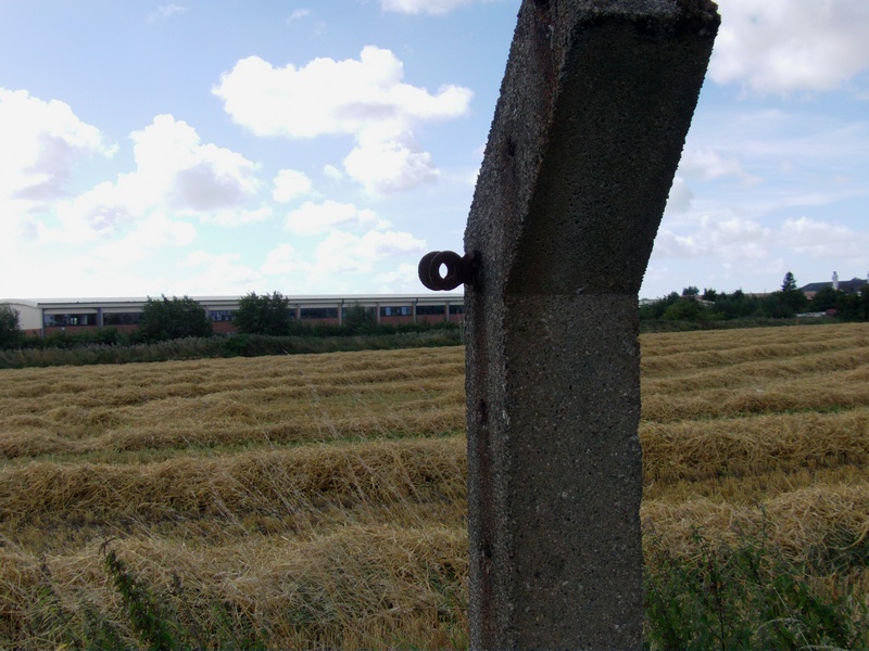
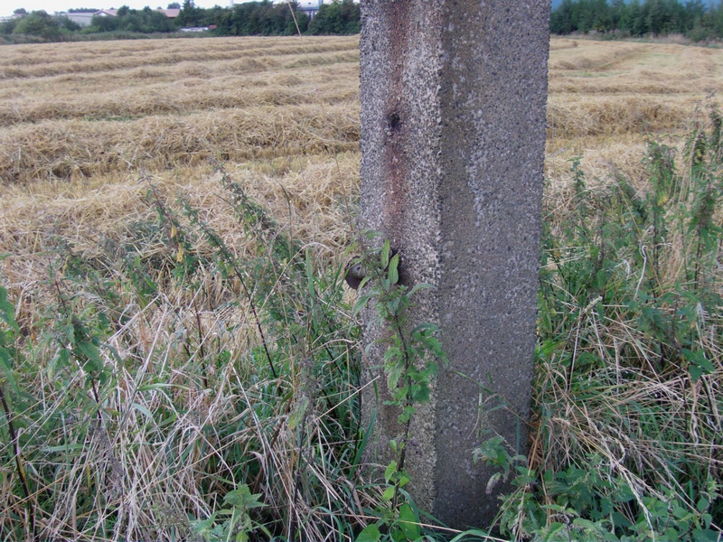
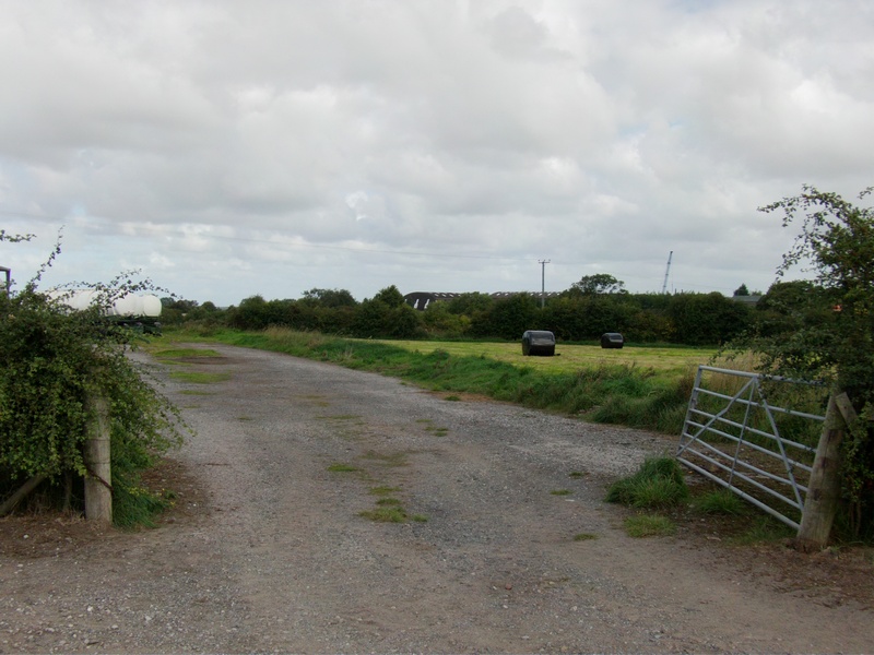
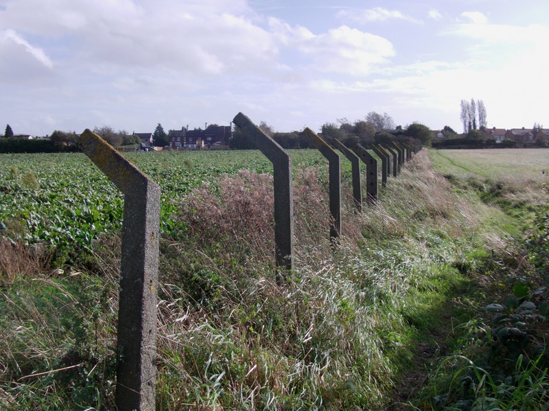
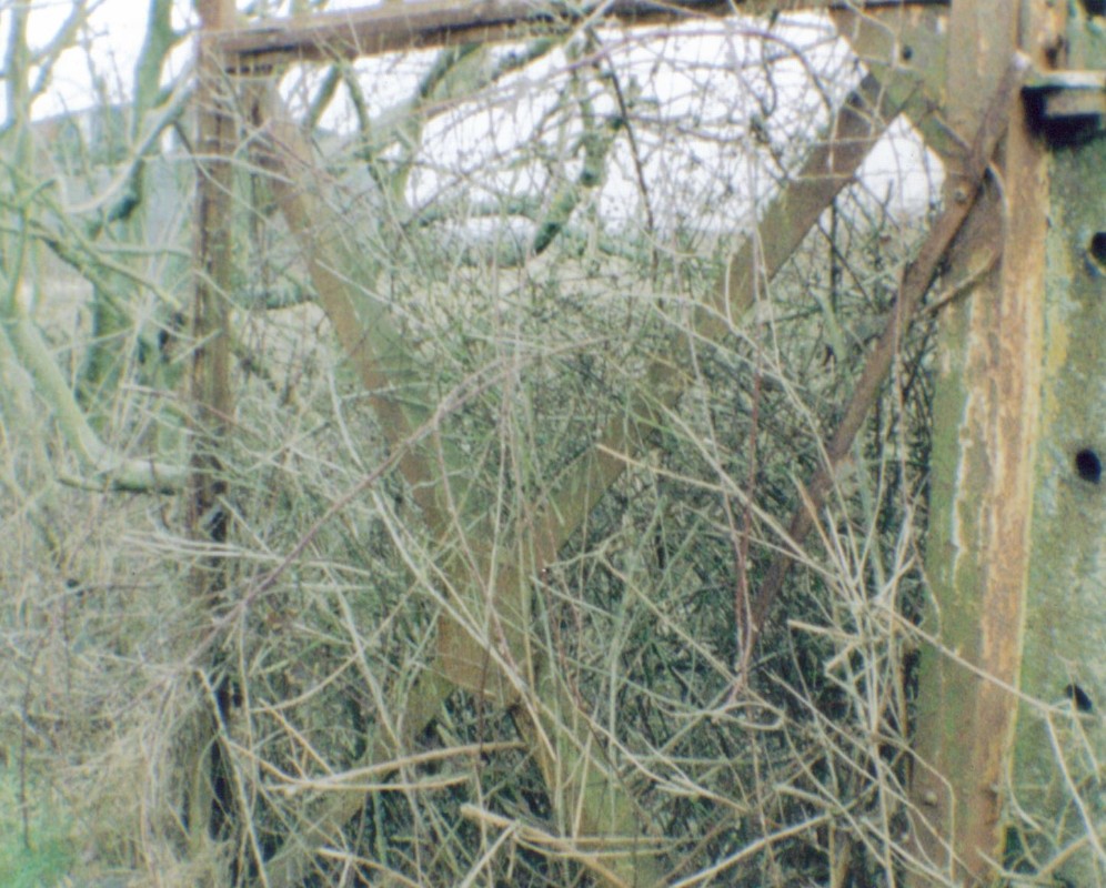
Higgins Lane Perimeter Fence Photos 2014 (at the back of Camp 3) The thickest post (the 5th post along in the photo) has ratchet strainers to tension the barbed wire through the other posts. These thickest posts are at each corner and are also spaced out every 10th post along the length of the actual fence itself and wires would have been fixed on the front (the face that is showing).
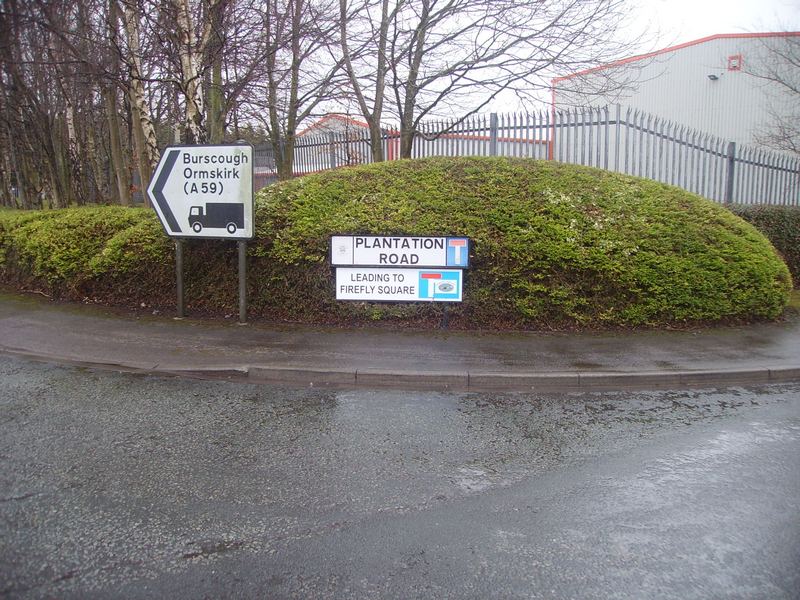
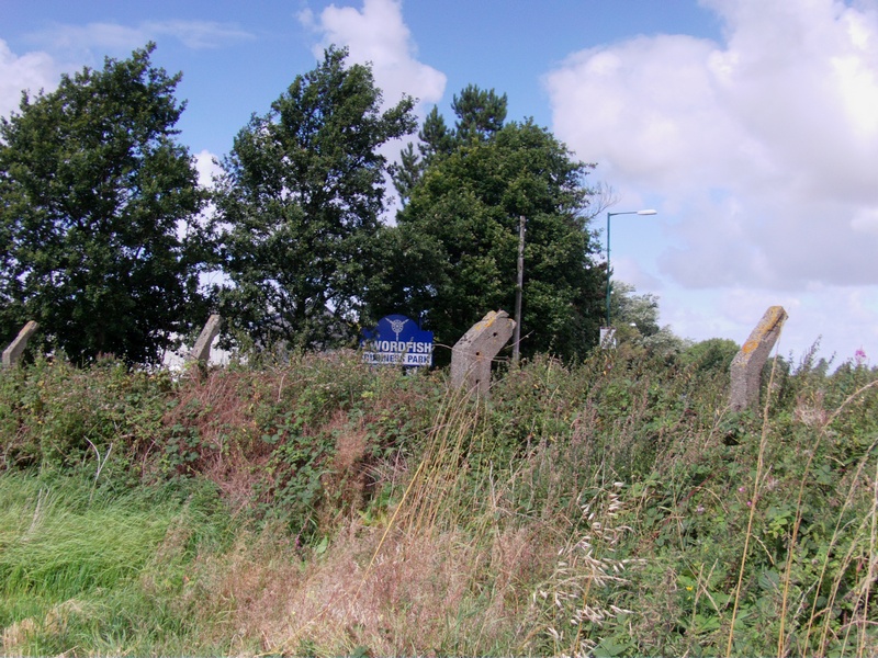
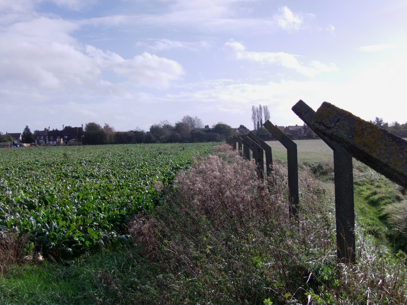
Higgins Lane Perimeter Fence Posts Continued (Note: The blue sign has a propeller on it and the industrial park now is called ‘Swordfish Business Park’)
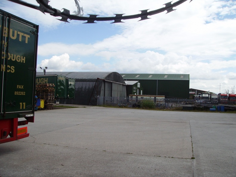
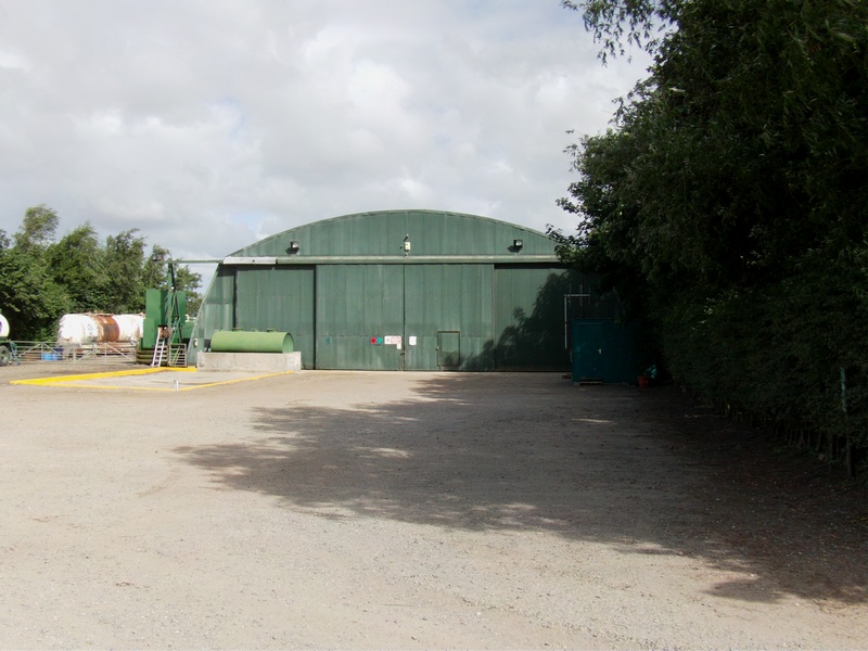
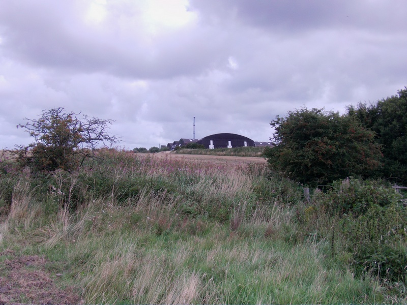
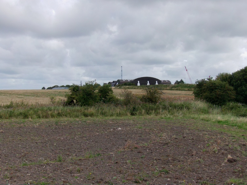
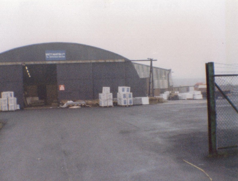
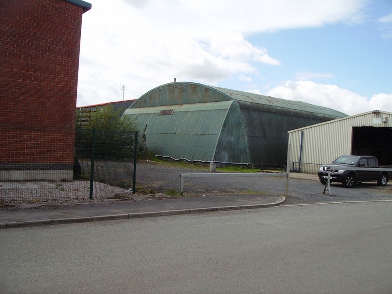
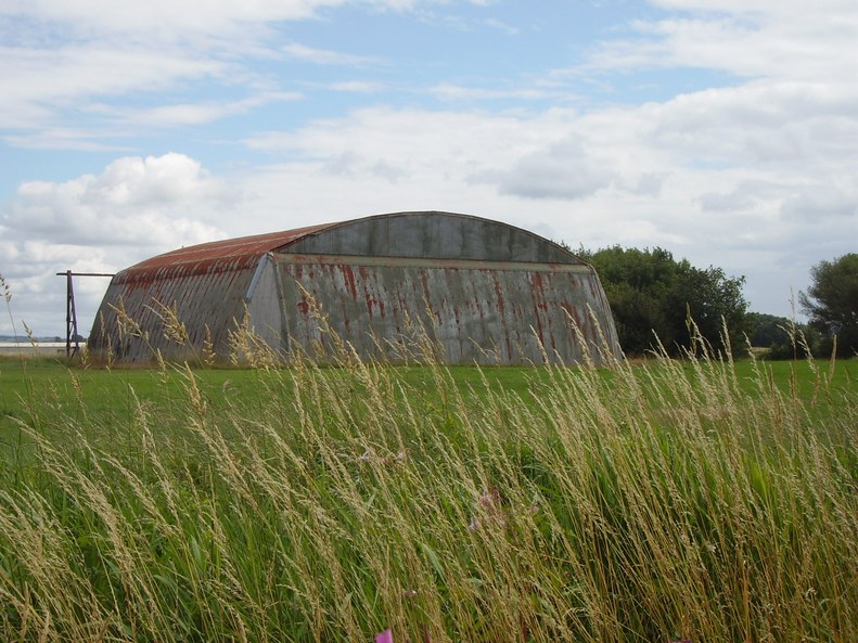
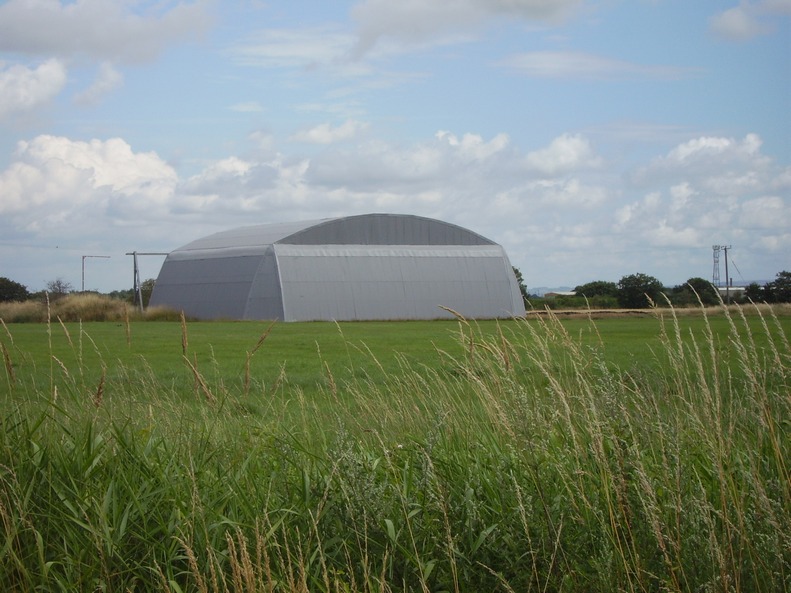
Radar Test Area Hangar 2014 The 3 larger hangars behind are NOT original, although they are built from other hangars from around the airfield
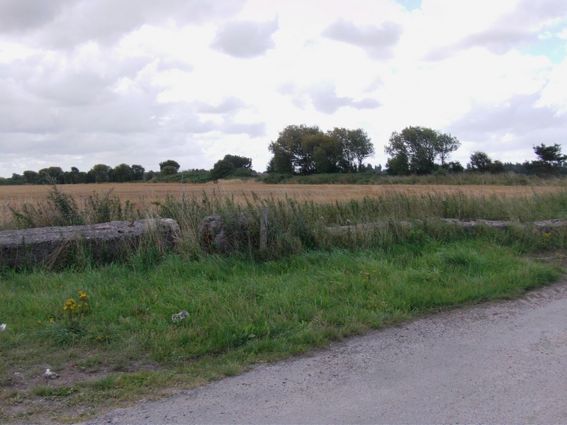
Runway Controllers Van Standing This is the remains of the exact area where the runway controllers van standing used to be. It is situated at the south end of runway 03/21.
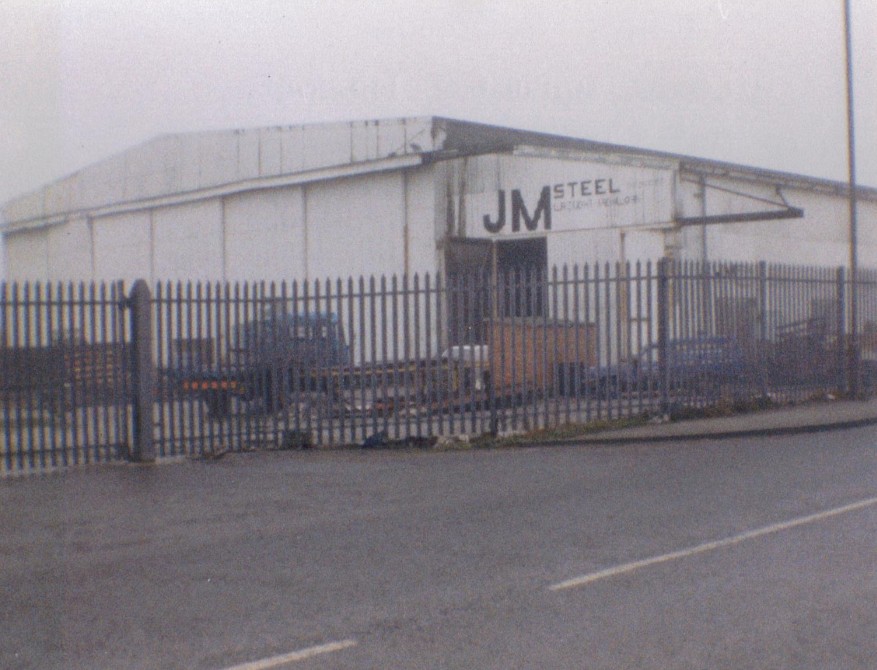
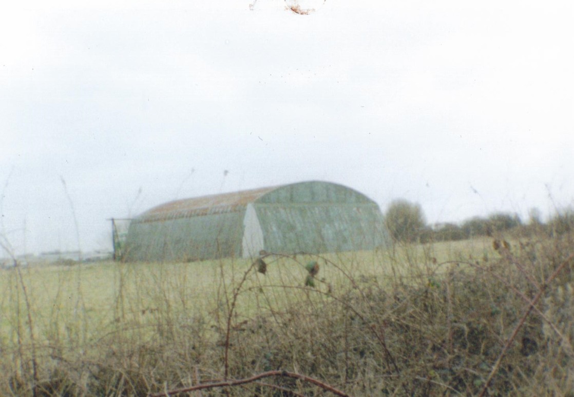
Pippin Street Dispersals 2004 Originally there was 6 mainhill admiralty type ‘s’ hangars. 4 still remain today in their original location on the airfield.
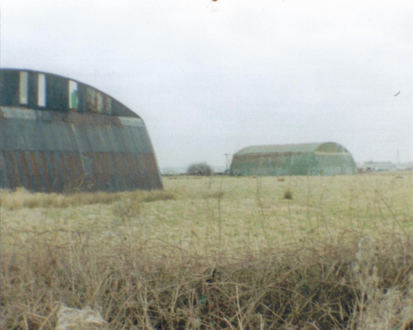
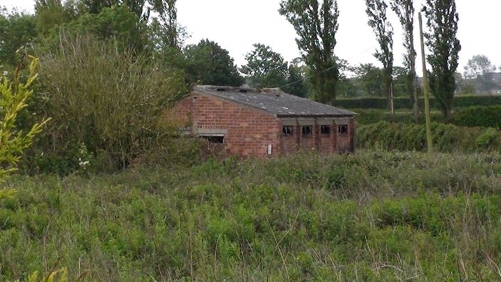
Pippin Street Dispersals (2014 though now) Continued … The building on the left of the photo is listed as a shelter but we think it was an electrical transformer plynth. In the background is a static water tank/emergency water supply.
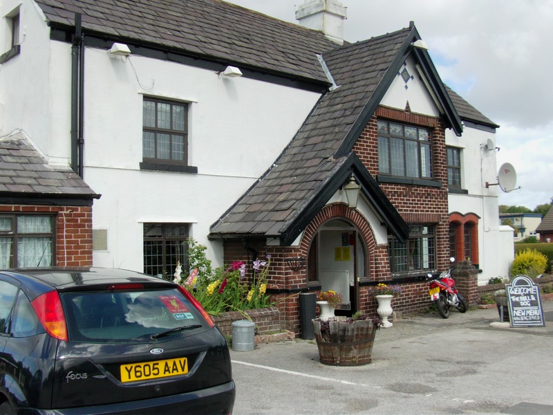
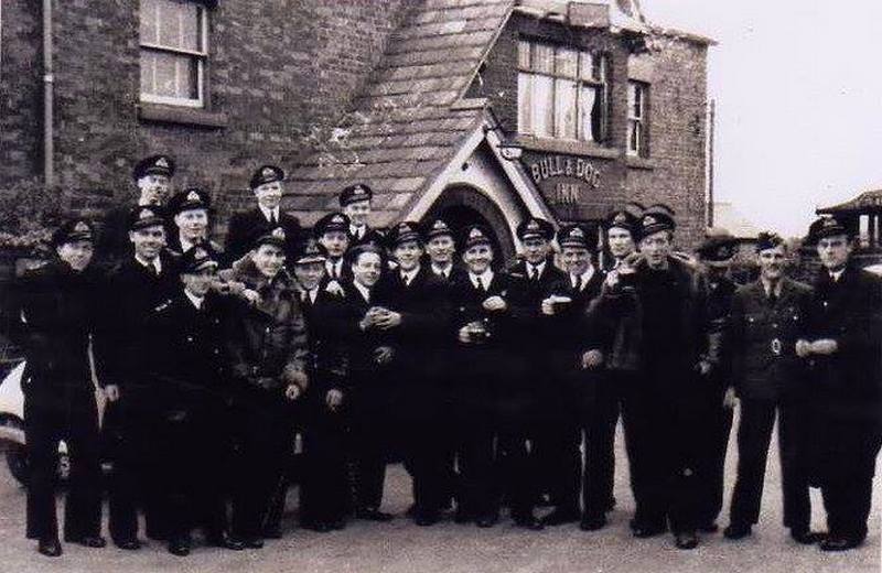
Bull & Dog 1944 1772 Squadron celebrate a 21st Birthday at the Bull and Dog in May 1944. This Squadron was formed at Burscough on 1st May 1944. The Bull and Dog was a regular ‘haunt’ for the Naval Personnel.
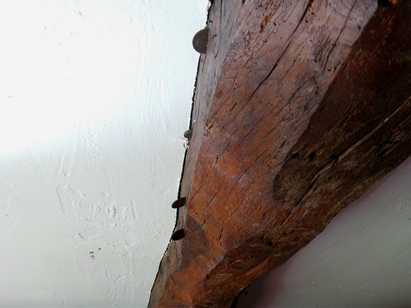
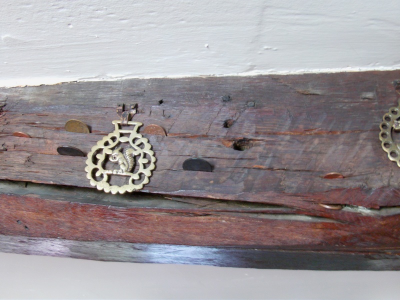
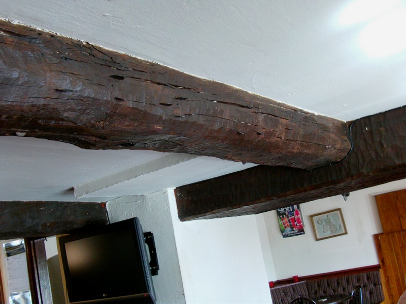
Bull & Dog (Inside) 2014 Royal Naval Personnel had a tradition of inserting coins into the wooden beams inside the pub … who knows, it could be some of the guys above?
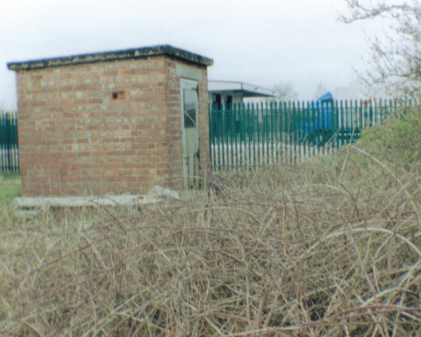
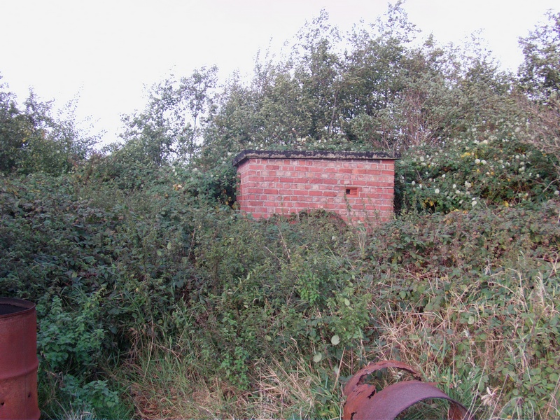
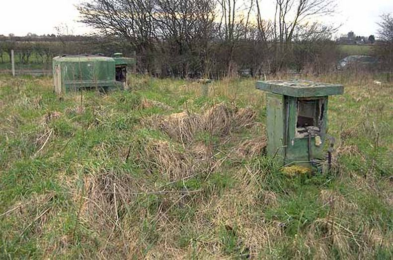
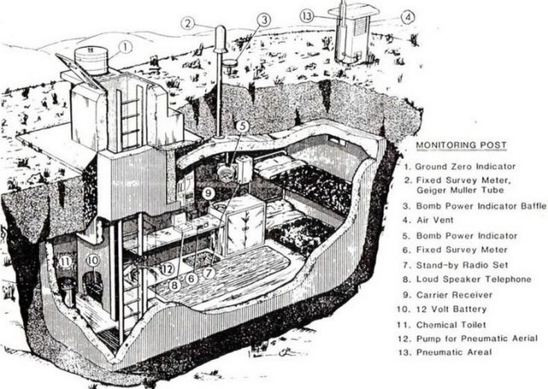
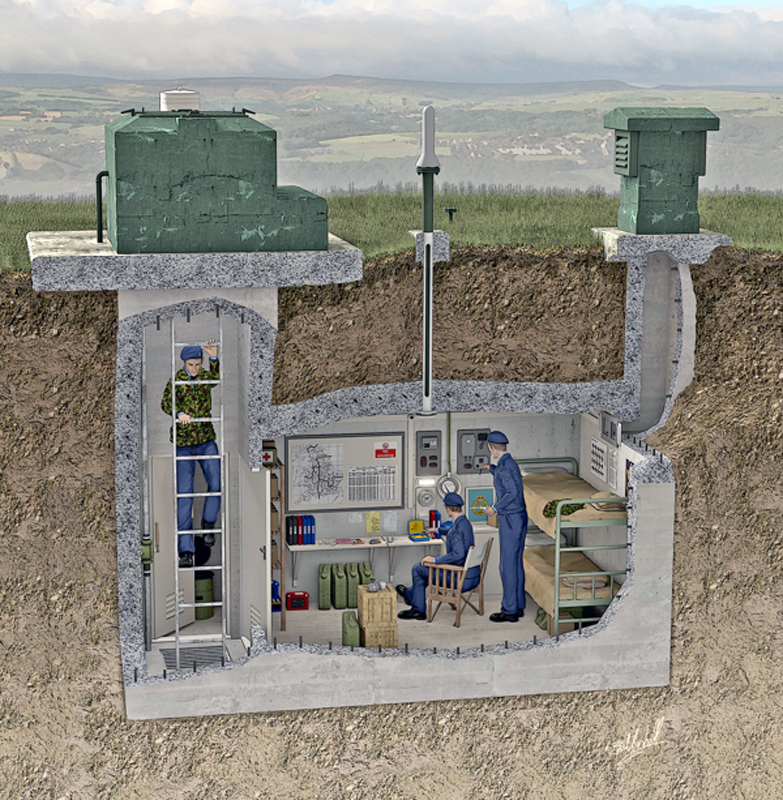
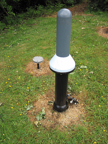
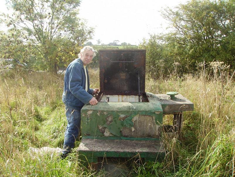
‘Cold War’ ROC (Royal Observer Corps) Monitoring Post United Kingdom Warning & Monitoring Organisation Burscough Lancashire.
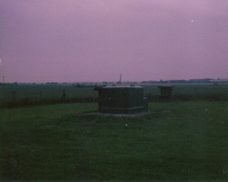
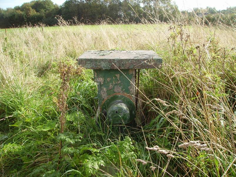
Picture of ROC Post Burscough Taken From a Different Angle When in Operation During the Cold War in 1984
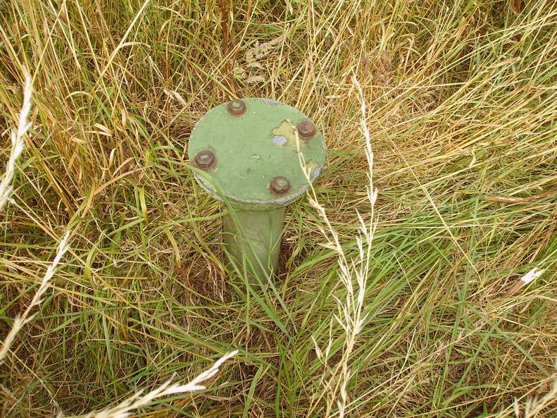
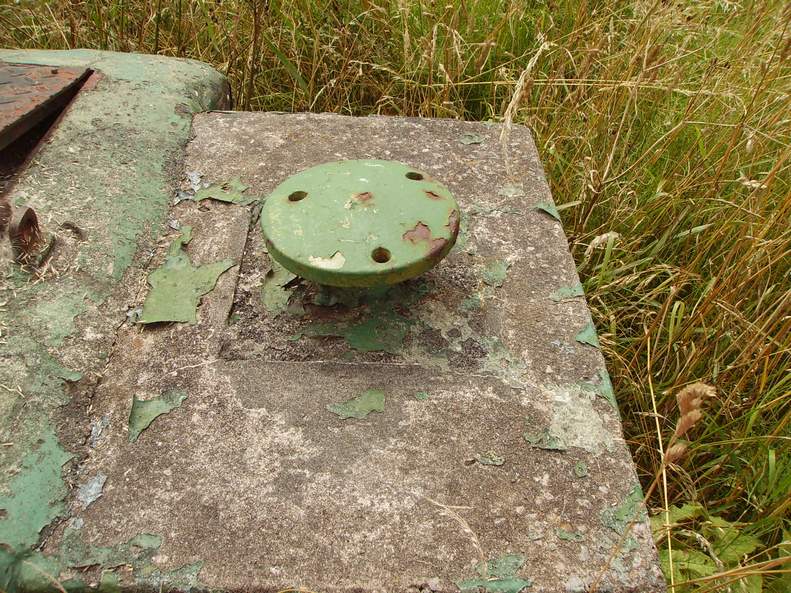
To take the dome cover off, there was a tool that was used that was inserted into the 2 holes to gain access to the aerial conections
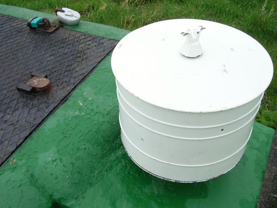
Behind The Dome (This is the view behind the dome. It shows the aerial coax cable leading down the ventilation shaft to the monitoring room)
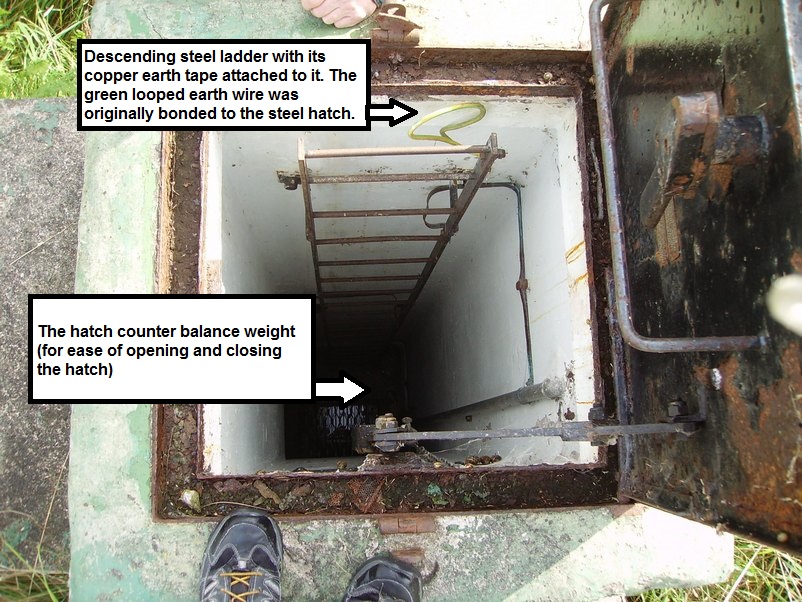
Furse copper earth strapping was installed from a ground point a few feet away from the ventilation shaft and was then routed down the ventilation shaft and fitted to all corners of the ceiling below ground and it was also cross bonded to the dome lid cover, the fixed survey meter pipe, bomb power indicator pipe and also the sump pipe discharge, ladder and had a loop of wire even on the hatch lid. This was used as a safety measure in case lightning hit the radio mast and potentially killed the occupants.
This is the aerial mast bracket which was originally fitted to the ventilation stack The aerial was telescopic and could be raised and lowered by an air hose by a foot pump in the monitoring room. When not in use, the aerial mast was stored in the entrance shaft next to the ladder.
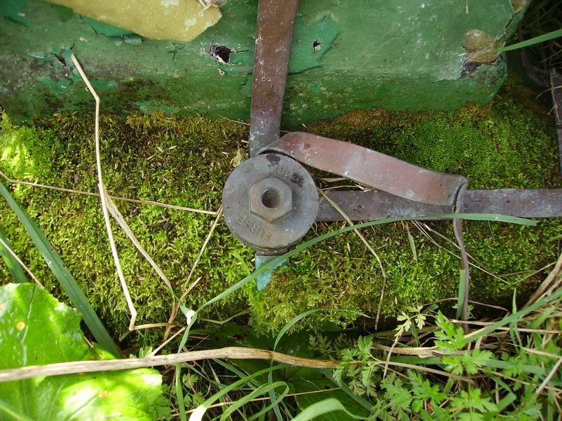
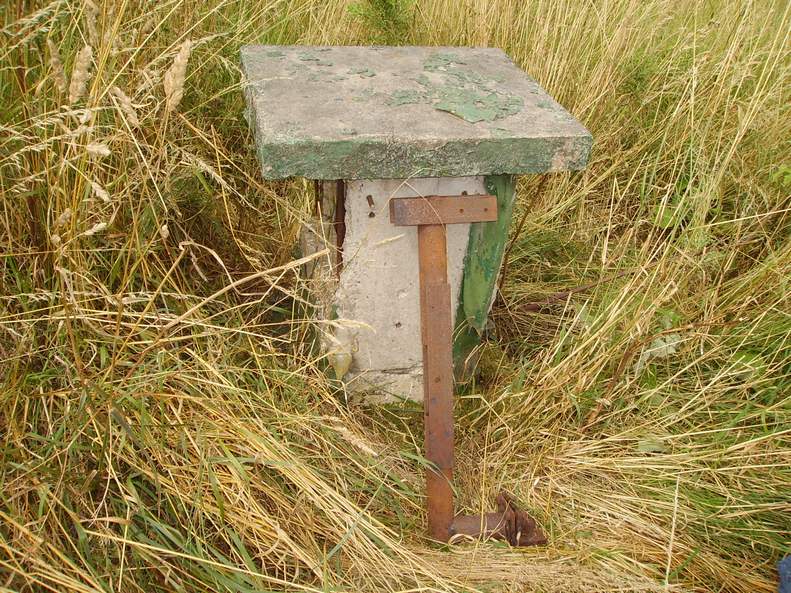
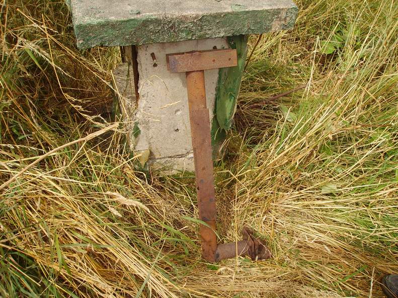
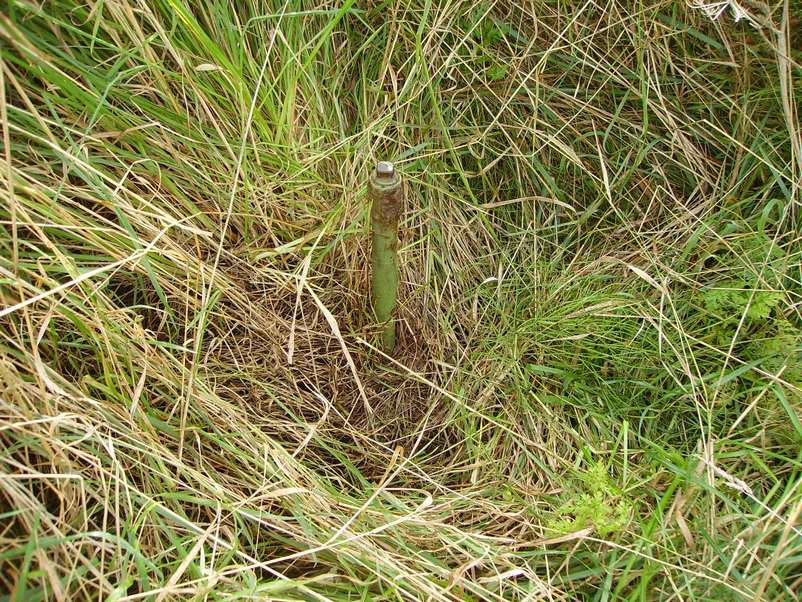
Fixed Survey Meter Pipe (With its blanking plate fitted) When the post was operational the blanking plate was removed by unscrewing the 4 bolts and fitted with a polycarbonate dome cover, in which the guiger muller head was then inserted through the roof flange below ground. This was used for measuring radiation fallout readings.
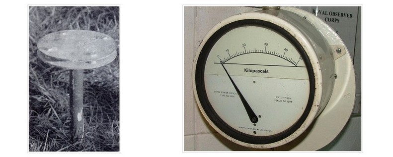
Fixed Survey Meter with Polycarbonate Cover Fitted (Note: In the background is the bomb power indicator baffle plate)
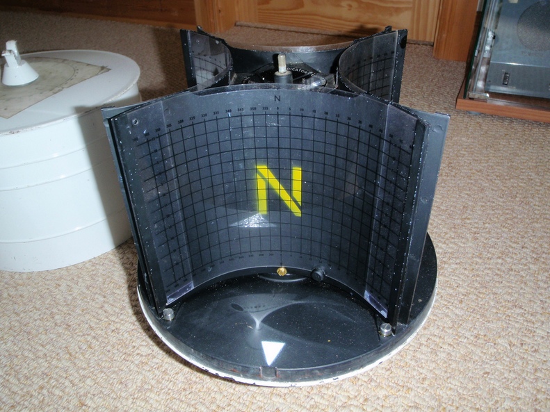
Ground Zero Indicator Mounting Bracket The ground zero indicator consisted of a 4 pin hole camera with light sensitive photographic paper (called shadow graph) in 4 photographic cassettes and were aligned with the cardinals of the compass to determine the direction and height of a nuclear blast.
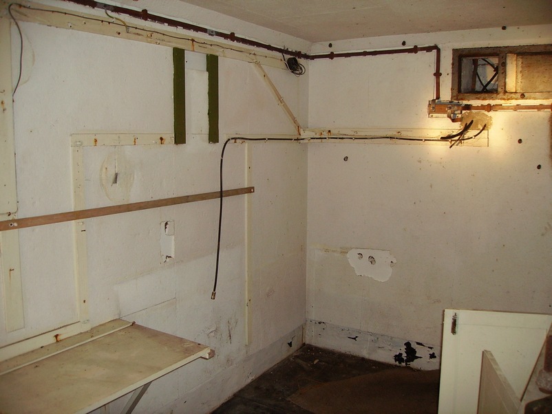
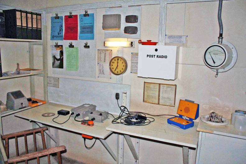
The Burndept VHF BE525 Radio Transmitter/Receiver Position The 2 black lines (below) is where the radio cabinet of the Burndept BE525 VHF transmitter radio/receiver was sited. The frequency of Burscough & 21 group was 80.3125 Channel 2 CER, Chanel 3 NWA, Code PRE (Note the actual aerial lead dangling down underneath the 2 black lines)
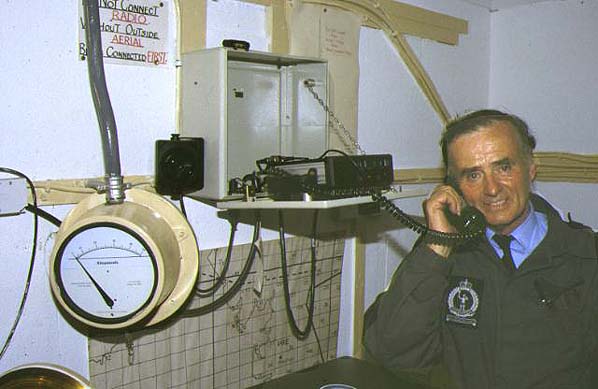
The Burndept VHF BE525 Radio Transmitter/Receiver osition Actually in Use/Example Although this is not a photo of Burscough’s ROC post, this example shows observer Harry Wilkinson at 21 group post at Fleetwood actually using the Burndept VHF BE525 radio. (Note the bomb power indicator at the bottom left with its blast pipe connected from the surface)
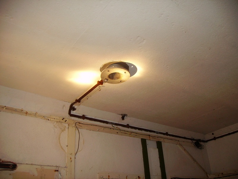
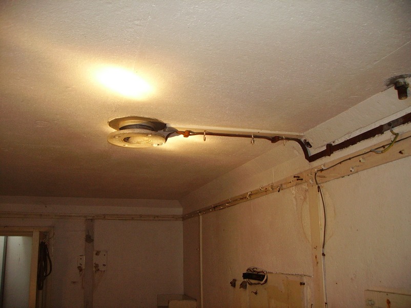
The Fixed Surface Meter Flange This photo shows the Fixed Surface Meter flange on the ceiling of the monitoring room. Note the furse copper earth bonding tape connected to it.
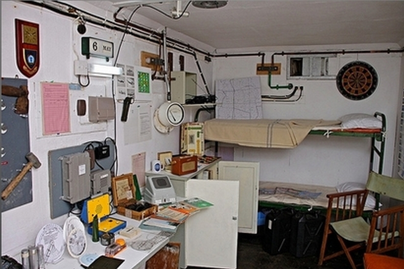
The Carrier Warning Receiver (after next photo) was Sited to The Left above the Monitoring Room Table
The Air Vent with its Steel Shutter Note the furse copper Earth tape bonding connection running under and round the sides of the vent. The bottom earth tape goes through the wall and runs up the ventilation shaft above ground bonding connection. Note also the black cables going through the wall. These also run up the ventilation shaft and are for the aerial mast.
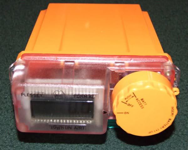
The View From the Back Wall Towards the Monitoring Room Door (Turn left through the door to the entrance shaft ladder & turn right to the chemical toilet room.) Please note: If you look at the desktop/table you can see a rectangular slot in it. This is roughly where the Plessey Radiac Meter was situated.
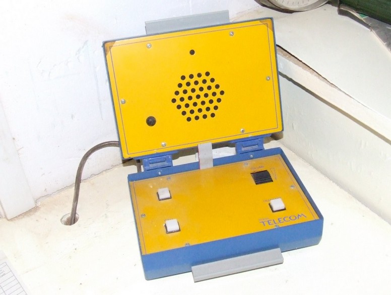
The Teletalk Type AD 8010 Also on the monitoring room table was the loudspeaker telephone and was known as a TeleTalk Type AD 8010 and was connected to a dedicated private land line circuit to 21 group headquarters at Lingley Lane Preston by simply pressing a call button. The other posts in the cluster could talk amongst themselves without involving group headquarters.
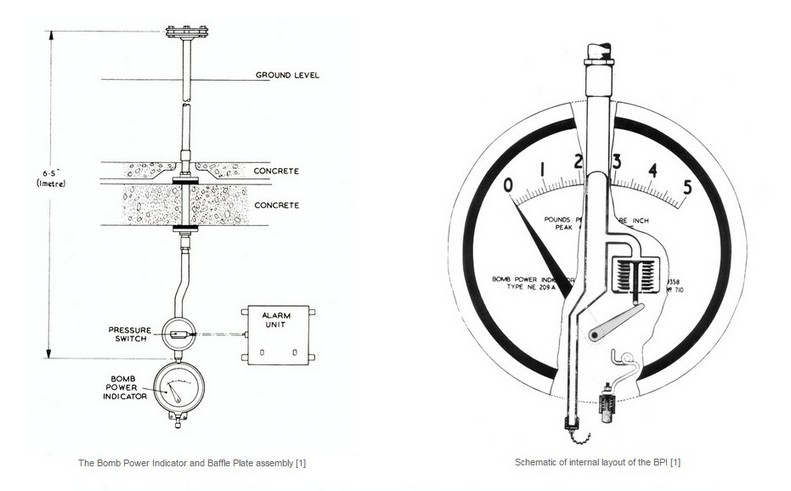
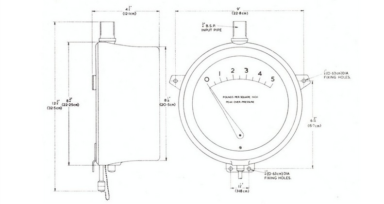
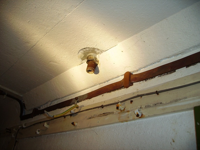
Bomb Power Indicator Blast Pipe Connection Point Note the green and yellow bonding cable which would have had an earth clamp fitted to the blast pipe
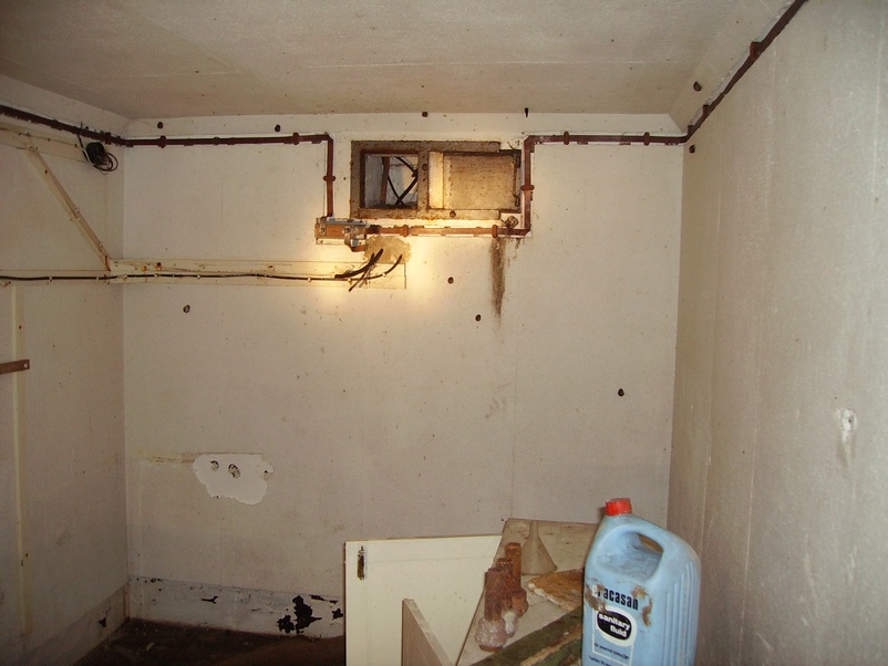
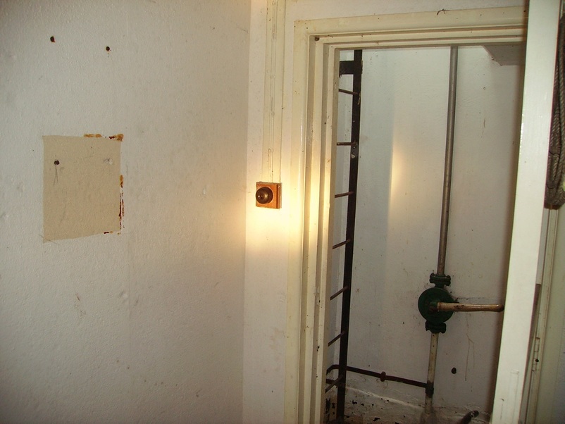
The Monitoring Room Entrance Door View From Inside the Monitoring Room The square on the left is where the emergency fire blanket was situated. The monitoring room light switch is unusual because most post were fitted with a timed light switch.
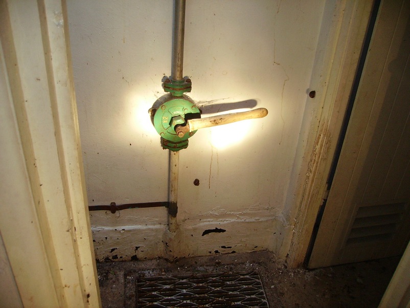
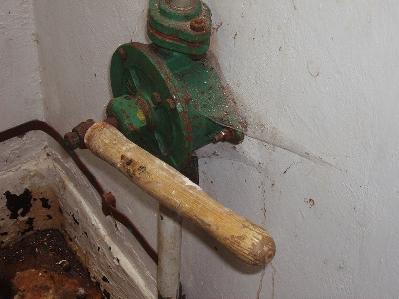
Water Discharge Pump The photo below is of the water discharge pump. This was used as a hand pump to pump out the water from the sump below the grill (below) to the outside above ground. Note the furse copper earth bonding attached to the pipe at the bottom of the pump.
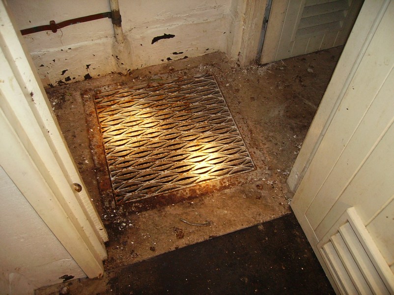
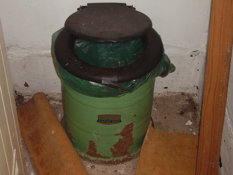
Close up of the Water Discharge Pump Grill (The chemical toilet is through the door opening on the right and to the left is the access ladder to the outside/surface)
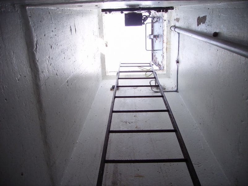
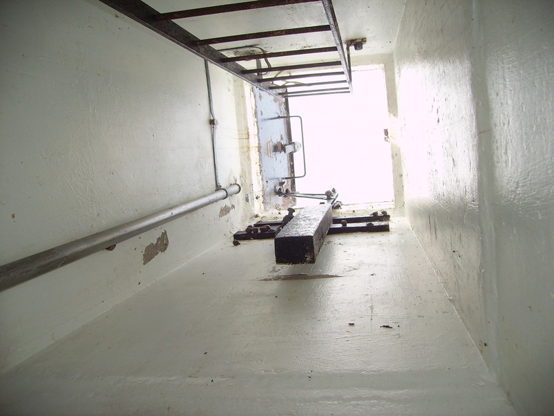
Entrance/Exit Shaft Leading to Outside/Surface The hatch lid counter balance is the large rectangular weight in the centre of the image. The long pipe coming from the left of the photo is the water sump discharge pipe. Note the furse copper earth bonding tape attached to the discharge pipe and cross-bonded to the steel ladder.
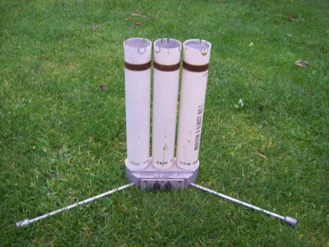
Maroon Rockets To warn the local public of nuclear fallout radiation, 3 projectile/rockets. known as ‘maroon rockets’ were sent high into the sky and then exploded making 3 large bangs in quick succession.
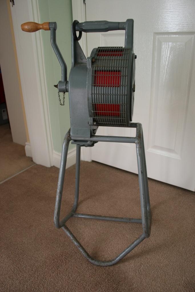
A Hand-Cranked Sekomak 447 Warning Siren A hand cranked warning siren positioned above ground was sounded to warn the local public of a nuclear attack. 2 different sounds were used. 1 rising and falling sound was to warn of an attack and 1 continuous sound was for the all clear.
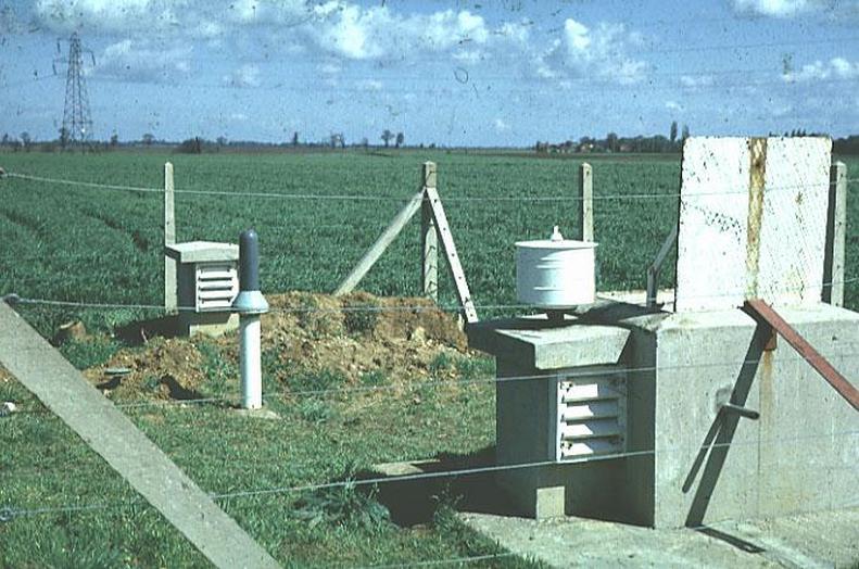
An Example of an ROC Post Showing Such Features as the Ground Zero Indicator Mounted on the Side of the Hatch & the Fixed Survey Meter with its Polycarbonate Cover Fitted
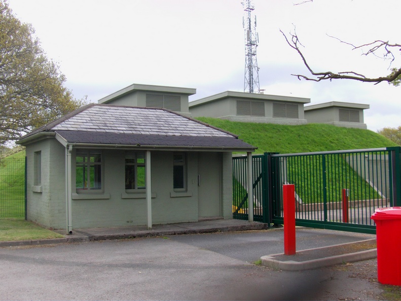
ROC 21 Group Headquarters & UKWMO National Protected Group Headquarters Langley Lane Goosnargh Preston Lancashire (The guard room in the foreground dates back to WW2. Note the 3 huge air exhausts/vents on the roof)
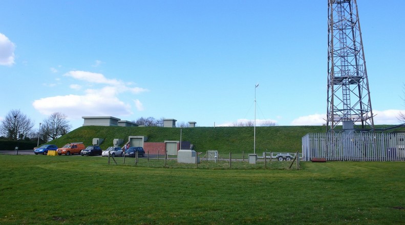
Side view of the bunker The 100 foot high aerial mast is now used by a communications company. Note: The site is now owned by a CCTV monitoring company
© Historic Aviation Military — All rights reserved Non Commercial — Non Profit Website / Organisation